background image

32

AV COMPU LINK Remote Control System

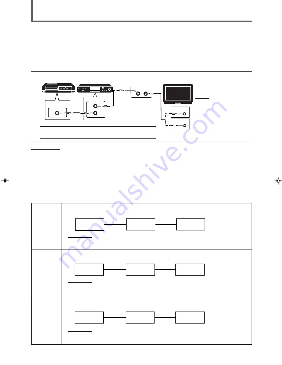
The AV COMPU LINK remote control system allows you to operate JVC’s video components (TV, VCR, and DVD player) through the
receiver.
This receiver is equipped with the AV COMPU LINK-III, which added a function to operate JVC’s video components through the video
components terminals. To use this remote control system, you need to connect the video components you want to operate, following the
diagrams below and the procedure on the next page.

CONNECTIONS 1: AV COMPU LINK Connection

AV

COMPU LINK

VHS

AV

COMPU LINK

AV

COMPU LINK EX

DVD

AV

COMPU LINK III

AV

COMPU LINK – III

TV

Note:

You can only connect to the TV
with the AV COMPU LINK EX or
AV COMPU LINK III terminal.
The TV with AV COMPU LINK
RECEIVER/AMP terminal will
not be used.

VCR

DVD player

IMPORTANT:

The AV COMPU LINK remote control system cannot control the DBS tuner
connected to the TV SOUND/DBS and DBS COMPONENT VIDEO terminals.

Notes:

• When connecting the receiver and a TV with the AV COMPU LINK EX terminal by using a component video cable, you cannot use Automatic

Selection of TV’s Input Mode (see page 33).

• When connecting only the VCR or DVD player to this receiver, connect it directly to the receiver using cables with the monaural mini-plugs.
• Make sure that the remote control code of the VCR connected to the VCR jacks is set to code “A.”
• Refer also to the manuals supplied with your video components.

CASE 1

When connecting the source equipment to the receiver using the S-video terminals, connect also this
receiver to the TV’s Video Input 1 terminal using S-video cables.

Note:

If you connect the DVD player and the DBS tuner to this receiver using the S-video terminals, change the video input
terminal setting to “S/C” (see page 16).

When connecting the source equipment to the receiver using the composite video terminals, connect also
this receiver to the TV’s Video Input 2 terminal (composite video input) using composite video cables.

Note:

If you connect the DVD player and the DBS tuner to this receiver using the composite video terminals, change the video
input terminal setting to “S/C” (see page 16).

When connecting the source equipment to the receiver using the component video terminals, connect also
this receiver to the TV’s Video Input 2 terminals (component video input) using component video cables.

Note:

If you connect the DVD player and the DBS tuner to this receiver using the component video terminals, change the
video input terminal setting to “COMPONENT” (see page 16).

CASE 3

CASE 2

To Video Input 1

TV

RX-7022VSL

S-video cable

S-video cable

Source

Equipment

CONNECTIONS 2: Video Cable Connections

This receiver is equipped with three types of video terminals — S-video, composite video, and component video — and the signals coming
into this receiver through one type of video terminal can output only through the same type of the terminal. So you need to connect the VCR
and/or DVD player to the TV using one of the following three ways:

To Video Input 2

(Composite)

TV

RX-7022VSL

Composite
video cable

Source

Equipment

Composite
video cable

To Video Input 2

(Component) 

TV

RX-7022VSL

Component
video cable

Source

Equipment

Component
video cable

EN30-42.RX-7020V[A]3

02.4.17, 5:16 PM

32

Содержание RX-7022RBK

Страница 1: ...N OFF SURROUND MODE PHONES SURROUND ON OFF FM AM TUNING STANDBY STANDBY ON FM AM PRESET FM MODE MEMORY INPUT ATT FM AM DVD MULTI PHONO SOURCE NAME 1 2 COMPULINK Remote CONTROL 2 3 1 5 6 4 8 9 7 P 0 10 10 BASSBOOST EFFECT MENU ENTER TEST REAR L DIMMER SUBWOOFER REAR R MUTING CH TVVOL REW FF VOLUME CA TV DBS CONTROL TV VIDEO REC PAUSE RETURN FMMODE 100 CONTROL A V CONTROL RECEIVER RM SRX7022U REMOTE...

Страница 2: ... Do not block the ventilation openings or holes If the ventilation openings or holes are blocked by a newspaper or cloth etc the heat may not be able to get out Do not place any naked flame sources such as lighted candles on the apparatus When discarding batteries environmental problems must be considered and local rules or laws governing the disposal of these batteries must be followed strictly D...

Страница 3: ...k and fire and to protect from damage Locate the apparatus as follows Front No obstructions open spacing Sides No obstructions in 10 cm from the sides Top No obstructions in 10 cm from the top Back No obstructions in 15 cm from the back Bottom No obstructions place on the level surface In addition maintain the best possible air circulation as illustrated ...

Страница 4: ... Signal 19 Adjusting the Front Speakers Output Balance 19 Adjusting the Tone 20 Adjusting the Subwoofer Output Level 20 Reinforcing the Bass 20 Tuner Operations 21 Tuning in Stations Manually 21 Using Preset Tuning 21 Selecting the FM Reception Mode 22 Creating Realistic Sound Fields 23 About Relations between Speaker Layouts and Surround Modes 25 Using Dolby Pro Logic II Dolby Digital and DTS Dig...

Страница 5: ...DVD CD TAPE CDR TREBLE TV DBS VCR PHONO FM AM BASS SURROUND ANALOG DIGITAL SLEEP SUBWOOFER REAR R REAR L CENTER SOUND Remote Control 1 Display window a Remote control operation mode indicator b Signal transmission indicator Lights up when transmitting the remote control signal 2 Power buttons 10 36 39 CATV DBS VCR TV AUDIO 3 Source selecting buttons 10 11 15 21 22 30 34 39 DVD DVD MULTI CD FM AM T...

Страница 6: ...t FM AM channels and sound adjustments may be erased in a few days Checking the Supplied Accessories Check to be sure you have all of the following supplied accessories The number in the parentheses indicates the quantity of the pieces supplied Remote Control 1 Batteries 2 AM Loop Antenna 1 FM Antenna 1 If anything is missing contact your dealer immediately Putting Batteries in the Remote Control ...

Страница 7: ...If the reception is poor connect an outdoor single vinyl covered wire not supplied to the AM EXT terminal Keep the AM loop antenna connected Notes If the AM loop antenna wire is covered with vinyl remove the vinyl while twisting it as shown to the right Make sure the antenna conductors do not touch any other terminals connecting cords and power cord This could cause poor reception Outdoor FM anten...

Страница 8: ...ng information properly to obtain the best possible Surround effects For details see pages 16 to 18 CAUTION Use speakers with the SPEAKER IMPEDANCE indicated by the speaker terminals Connecting the front speakers You can connect two pairs of front speakers one pair to the FRONT SPEAKERS 1 terminals and the other pair to the FRONT SPEAKERS 2 terminals About the speaker impedance The required speake...

Страница 9: ...minal on the rear panel Audio Components Video Components Turntable VCR CD player TV Cassette deck or DBS tuner or CD recorder DVD player Note Any turntables incorporating a small output cartridge such as an MC moving coil type must be connected to this receiver through a commercial head amplifier or step up transformer Direct connection may result in insufficient volume To audio output Ex This co...

Страница 10: ... video component are connected to the unit through the different types of video terminals you cannot view the playback picture from the playing component on the TV Å To left right channel audio output ı To left right channel audio input Ç To composite video output Î To S video output To S video input Ï To composite video input VCR AUDIO TV SOUND DBS VCR OUT REC IN PLAY TAPE CDR CD PHONO OUT REC IN...

Страница 11: ...B COMPONENT VIDEO MONITOR OUT DBS DVD Y PB CB PR CR VIDEO VCR OUT REC IN PLAY MONITOR OUT DVD DBS S VIDEO VIDEO DBS AUDIO TV SOUND DBS VCR OUT REC IN PLAY TAPE CDR CD PHONO OUT REC IN PLAY RIGHT LEFT REAR RIGHT LEFT FRONT CENTER DVD SUBWOOFER OUT SUB WOOFER RIGHT LEFT B A C D AUDIO Å To audio output ı To composite video output Ç To S video output Î To component video output Notes When connecting t...

Страница 12: ... correctly if necessary Set the digital input DIGITAL IN terminal setting correctly For details see Setting the Digital Input DIGITAL IN Terminals on page 14 Select the digital input mode correctly For details see Selecting the Analog or Digital Input Mode on page 15 Digital input terminals Before connecting a digital optical cable unplug the protective plug Digital optical cable not supplied betw...

Страница 13: ... source name on page 11 When you have connected some digital source components using the digital terminals see page 9 you need to select the digital input mode see page 15 When you press one of the source selecting buttons on the remote control marked above with asterisks the receiver automatically turns on On the front panel From the remote control DVD VCR TV SOUND DBS CD TAPE CDR SOURCE NAME FM ...

Страница 14: ... either the speakers connected to the FRONT SPEAKERS 1 or 2 terminals Changing the source name When you have connected a CD recorder to the TAPE CDR jacks or the DBS tuner to the TV SOUND DBS jacks on the rear panel change the source name which will be shown on the display When changing the source name from TAPE to CDR 1 Press TAPE CDR SOURCE NAME to select TAPE as the source 2 Press and hold SOUR...

Страница 15: ... appears and H PHONE indicator lights up on the display This cancels the Surround modes currently selected and activates the HEADPHONE mode see below HEADPHONE mode When using the headphones following signals are output regardless of your speaker setting For 2 channel sources the front left right channel signals are output directly from the headphones For multichannel sources the front left and ri...

Страница 16: ...ngs are not possible The output volume level bass boost see page 20 tone adjustment see page 20 and Surround modes see page 23 cannot affect the recording The test tone signal see pages 26 and 27 does not come out through the DIGITAL OUT terminal Basic Operations Signal and speaker indicators on the display The following signal indicators light up L When digital input is selected Lights up when th...

Страница 17: ...ALOG DIGITAL LINEAR PCM 1 2 R Source Selecting Buttons INPUT ANALOG DIGITAL CONTROL UP 5 DOWN Display SETTING CONTROL DOWN UP L C S WFR LS RS CH S LFE SPK DIGITAL AUTO 1 R When the DIGITAL 1 terminal is set the DIGITAL 2 3 4 terminals are set automatically as follows When the DIGITAL 1 is set to DVD 2 CD 3 TV or DBS 4 CDR When the DIGITAL 1 is set to CD 2 DVD 3 TV or DBS 4 CDR When the DIGITAL 1 i...

Страница 18: ...om the remote control If the following symptoms occur while playing Dolby Digital or DTS Digital Surround software with DIGITAL AUTO selected follow the procedure below Sound does not come out at the beginning of playback Noise comes out while searching or skipping chapters or tracks 1 Press INPUT ANALOG DIGITAL or ANALOG DIGITAL INPUT on the remote control 2 Press CONTROL UP 5 DOWN to select DOLB...

Страница 19: ...AR PCM 1 R ST SETTING NO for the subwoofer LARGE for the front speakers and SMALL for the center and rear speakers are initial settings To get best possible sound change the subwoofer and speaker settings to fit your listening conditions Setting the Speaker Information To obtain the best possible sound or effect from Surround modes see pages 26 to 29 register the following speakers and subwoofer i...

Страница 20: ...aker distance Register the unit you use then the speaker distance from your listening point If you have set the unit before start from step 3 Speaker distance is not valid for the DVD MULTI playback mode T SETTING CONTROL DOWN UP L C S WFR LS RS CH S LFE SPK DIGITAL AUTO LINEAR PCM 1 R T SETTING CONTROL DOWN UP 3 0 m 10 feet Left front speaker Right front speaker Right rear speaker Left rear speak...

Страница 21: ...igned from small speaker to large speakers To use this function properly set this crossover frequency level according to the size of the small speaker connected If you have selected LARGE for all speakers this function will not take effect Crossover frequency is not valid for the DVD MULTI playback mode and HEADPHONE mode 1 Press SETTING repeatedly until CROSS Crossover with the current setting ap...

Страница 22: ...OOST INPUT ATT Adjusting the Front Speakers Output Balance If the sounds you hear from the front right and left speakers are unequal you can adjust the speakers output balance Before you start remember There is a time limit in doing the following steps If the setting is canceled before you finish start from step 1 again 1 Press ADJUST repeatedly until BALANCE with the current setting appears on th...

Страница 23: ...o activate the bass boost function The BASS BOOST indicator lights up on the display Select BASSBOOST OFF to cancel it The indicator goes off Note This function affects the front speaker sounds only BASSBOOST From the remote control On the front panel BASS BOOST L C S WFR LS RS CH S LFE SPK DIGITAL AUTO LINEAR PCM 1 R Adjusting the Tone You can adjust the bass and treble sounds as you like On the ...

Страница 24: ...EREO VOLUME ANALOG 1 R Ex When the FM band is selected FM AM TUNING TUNING On the front panel From the remote control Using Preset Tuning Once a station is assigned to a channel number the station can be quickly tuned You can preset up to 30 FM and 15 AM stations To store the preset stations Before you start remember There is a time limit in doing the following steps If the setting is canceled bef...

Страница 25: ...e control be sure that they are activated for the tuner not for the CD and others See page 34 FM AM FM AM PRESET L C S WFR LS RS CH S LFE SPK AUTOMUTING TUNED STEREO VOLUME ANALOG 1 R MEMORY L C S WFR LS RS CH S LFE SPK AUTOMUTING TUNED STEREO VOLUME ANALOG 1 R FM AM 2 3 1 5 6 4 8 9 7 P 0 10 10 EFFECT TEST RETURN FMMODE 100 SUBWOOFER REAR R REAR L CENTER MENU ENTER Selecting the FM Reception Mode ...

Страница 26: ...sed to reproduce multichannel sound tracks of the software encoded with Dolby Digital D I G I T A L To enjoy the software encoded with Dolby Digital connect the source component using the digital terminal on the rear of this receiver See page 9 Dolby Digital 5 1 ch encoding method so called discrete multichannel digital audio format records and digitally compresses the left front channel right fro...

Страница 27: ...vided with this receiver LIVE CLUB Gives the feeling of a live music club with a low ceiling DANCE CLUB Gives a throbbing bass beat HALL Gives clear vocal and the feeling of a concert hall PAVILION Gives the spacious feeling of a pavilion with a high ceiling These DAP modes can be used to add the acoustic surround effects while reproducing 2 channel stereo software either analog or digital except ...

Страница 28: ...TO LINEAR PCM 1 R SURROUND OFF PL II MOVIE or PL II MUSIC SURROUND ON OFF Ex PL II MUSIC has been selected Turning on or off the Surround modes Front speaker Front speaker Remote Front panel SURROUND MODE L C S WFR LS RS S LFE SPK PROLOGIC ΙΙ DSP H PHONE AUTOMUTING TUNED STEREO INPUT ATT DIGITAL AUTO LINEAR PCM 1 R PL II MOVIE PL II MUSIC Selecting the Surround modes Note When the digital multicha...

Страница 29: ...ASS SURROUND SURROUND ANALOG DIGITAL SLEEP SUBWOOFER REAR R REAR L CENTER SOUND RM SRX7022U REMOTE CONTROL SURROUND ON OFF EFFECT SOUND TEST Using Dolby Pro Logic II Dolby Digital and DTS Digital Surround Once you have adjusted the Surround modes the adjustment is memorized for each source When playing back digital multichannel software Dolby Digital 5 1 ch or DTS Digital Surround the SURROUND MOD...

Страница 30: ...activate Surround mode Each time you press the button Surround mode turns on and off alternately If you are playing back software encoded with Dolby Digital multichannel DOLBY DIGITAL is selected If you are playing back software encoded with DTS Digital Surround DTS SURROUND is selected If you are playing back any software other than above you can select PL II MUSIC or PL II MOVIE according to the...

Страница 31: ...will be convenient for you to use the remote control for adjustments since you can make adjustments from your listening point 1 Start playing 2 channel software either analog or Linear PCM and select the source 2 Press SURROUND ON OFF to activate Surround mode When the Surround mode turns on the last selected Surround mode will be activated Each time you press the button Surround mode turns on and...

Страница 32: ... adjust the center speaker output level 10 to 10 0 is the initial setting If you have already changed the setting another number level will be shown 2 Press CONTROL UP 5 DOWN to adjust the selected speaker output levels 3 Repeat steps 1 and 2 to adjust the other speaker levels 5 For DAP modes only Adjust the effect level 1 Press ADJUST repeatedly until EFFECT with the current setting appears on th...

Страница 33: ...tput mode on the DVD player and start playing a DVD Refer also to the manual supplied with the DVD player If you need to make any adjustments go to the following steps 3 Adjust the speaker output levels 1 Press ADJUST repeatedly until one of the following indications appears on the display CENTER To adjust the center speaker output level 10 to 10 REAR L To adjust the left rear speaker output level...

Страница 34: ...o use this remote control system you need to connect JVC s audio components through the COMPU LINK 4 SYNCHRO jacks see below in addition to the connections using cables with RCA pin plugs see pages 6 and 7 Make sure that the AC power cords of these components are unplugged before connection Plug the AC power cords only after all connections are completed Notes There are four versions of COMPU LINK...

Страница 35: ... video terminals connect also this receiver to the TV s Video Input 1 terminal using S video cables Note If you connect the DVD player and the DBS tuner to this receiver using the S video terminals change the video input terminal setting to S C see page 16 When connecting the source equipment to the receiver using the composite video terminals connect also this receiver to the TV s Video Input 2 t...

Страница 36: ... turn off Note If you turn off the receiver while recording on the VCR the VCR will not turn off but continue recording 1 If you have already plugged your VCR DVD player TV and this receiver into the AC outlets unplug their AC power cords first 2 Connect your VCR DVD player TV and this receiver as follows using the cables with the monaural mini plugs not supplied See CONNECTIONS 1 on the previous ...

Страница 37: ... rear speaker output level EFFECT Select the DAP effect level TEST Turn on or off the test tone output Note After adjusting sounds press the corresponding source selecting button or CONTROL to operate your target source by using the 10 keys otherwise the 10 keys cannot be used for operating your target source Tuner You can always use the following buttons FM AM Alternate between FM and AM After pr...

Страница 38: ... track number 12 and starting playback Press 1 0 5 then 1 2 then 3 Turntable After pressing PHONO you can perform the following operations on the turntable 3 Start playing 7 Stop operations Cassette deck After pressing TAPE CDR or CONTROL repeatedly until TAPE appears on the display window you can use the following buttons for cassette deck operations 3 3 3 3 3 Start playback FF Fast wind a tape f...

Страница 39: ...recording pause Press this button then 3 to start recording CH Change the TV channels on the VCR Note You can use either VCR button or CONTROL button to activate the buttons listed above If you press VCR the playing source also changes On the other hand if you press CONTROL repeatedly to select VCR the playing source does not change DVD player After pressing DVD or DVD MULTI source selecting butto...

Страница 40: ... the correct one is entered Manufacturer Codes JVC 00 02 13 14 47 74 AKAI 01 02 BLAUPUNKT 03 04 FISHER 01 05 GRUNDIG 03 06 07 HITACHI 08 09 10 49 IRADDIO 02 ITT NOKIA 11 12 LOEWE 06 15 16 MAGNAVOX 08 17 49 METS 50 51 52 53 MITSUBISHI 08 18 19 20 MIVAR 21 NORDMENDE 22 23 OKANO 15 PANASONIC 24 25 26 27 76 PHILIPS 15 17 28 75 QUELLE 52 53 54 55 56 57 58 59 60 61 62 63 64 65 66 67 RCA PROSCAN 08 24 29...

Страница 41: ...ding Note Refer also to the manual supplied with your VCR 5 Try to operate your VCR by pressing VCR When your VCR turns on or off you have entered the correct codes If there are more than one code listed for your brand of VCR try each one until the correct one is entered Manufacturers codes for CATV converter Manufacturer Codes GENERAL INSTRUMENT 06 07 08 09 10 11 12 13 14 29 HAMLIN REGAL 01 02 03...

Страница 42: ...y are changed this remote control cannot operate the equipment To change the transmittable signals for operating a DVD player 1 Press and hold AUDIO 2 Press DVD 3 Enter manufacturer s codes using buttons 1 9 and 0 4 Release AUDIO Now you can use the following buttons on the DVD player after pressing DVD or DVD MULTI source selecting button 3 Start playback 7 Stop playback Skip to the beginning of ...

Страница 43: ... your dealer Remove the obstruction Replace batteries Press SOUND or source selecting buttons first then press the button you want to use See pages 34 39 POSSIBLE CAUSE The power cord is not plugged in Speaker signal cables are not connected The SPEAKERS ON OFF 1 and 2 buttons are not set correctly An incorrect source is selected Muting is activated An incorrect input mode analog or digital is sel...

Страница 44: ... Digital and DTS Digital Surround with sampling frequency 32 kHz 44 1 kHz 48 kHz Audio Output Level TAPE CDR VCR 220 mV Digital output Optical DIGITAL OUTPUT Signal wave length 660 nm Output level 21 dBm to 15 dBm Signal to Noise Ratio 66 IHF DIN PHONO MM 70 dB 66 dB at REC OUT CD TAPE CDR VCR TV SOUND DBS DVD 87 dB 67 dB Frequency Response 8 Ω PHONO MM 20 Hz to 20 kHz 1 dB CD TAPE CDR VCR TV SOUN...

Страница 45: ...Monaural 0 4 at 1 kHz Stereo 0 6 at 1 kHz Stereo Separation at REC OUT 35 dB at 1 kHz Alternate Channel Selectivity 45 dB 400 kHz Frequency Response 30 Hz to 15 kHz 0 5 dB 3 dB AM tuner Tuning Range 522 kHz to 1 629 kHz Usable Sensitivity Loop antenna 400 µV m Signal to Noise Ratio 50 dB 100 mV m General Power Requirements AC 240 V adjustable with the voltage selector 50 Hz 60 Hz Power Consumption...

Страница 46: ...EN 0402NHMMDWJEIN J VC VICTOR COMPANY OF JAPAN LIMITED ...

Отзывы: