1-12 (No.MB159)
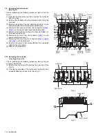
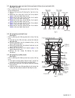
3.14 Removing the power supply board
(See Fig.16)
• Prior to performing the following procedure, remove the top
cover.
(1) From the top side of the main body, disconnect the parallel
wires from the connectors
CN203
and
CN241
on the power
supply board.
(2) Disconnect the card wire from the connector
CN201
on the
power supply board.
(3) Disconnect the relay board from the connector
CN291
on
the power supply board.
(4) Disconnect the parallel wire from the connector
CN101
on
the headphone jack board.
(5) Remove the solders from the soldered section
c
on the
power transformer board 1.
(6) Remove the two screws
U
and the screw
V
attaching the
power supply board.
(7) Remove the power supply board from the hook
g
of the
chassis base bracket in the direction of the arrow, take out
the power supply board.
(8) Turn over the power supply board, remove the solders from
the soldered sections
h
attaching the wires.
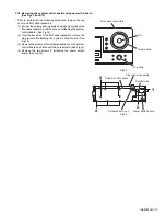
3.15 Removing the headphone jack board
(See Figs.16 and 17)
• Prior to performing the following procedure, remove the top
cover and front panel assembly.
(1) From the top side of the main body, disconnect the parallel
wire from the connector
CN101
on the headphone jack
board. (See Fig.16)
(2) From the front side of the main body, remove the nut and
screw
W
attaching the bracket(phones) to the chassis
base. (See Fig.17)
Fig.16
Fig.17
U
U
V
Card wire
CN201
CN101
Headphone jack
board
CN241
CN203
Relay
board
CN291
Power transformer board 1
Soldered
section
c
Soldered
section
h
Hook
g
of the
chassis base bracket
Parallel
wires
Parallel
wire
Power supply board
Headphone jack board
Nut
Chassis base
Bracket(phones)
W
Содержание RX-6040B
Страница 15: ... No MB159 1 15 SECTION 5 TROUBLESHOOTING This service manual does not describe TROUBLESHOOTING ...
Страница 19: ... M E M O ...
Страница 45: ... M E M O ...

