


1-24 (No.YA711<Rev.002>)
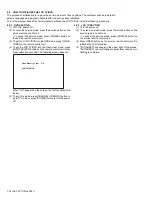
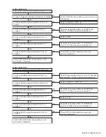
[ Video Signal Section ]
No
Is the "L" pulse sent out Pin(1) terminal of remote
control receiver (RS101) when the infrared remote
control is activated?
Check the line between Pin(1) terminal of remote
control receiver(RS101) and Pin(25) of CN301,
and service it if defective.
Yes
Is the "L" pulse supplied to Pin(25) of CN301?
Yes
Is 3.3V voltage supplied to Pin(2) terminal of the
remote control receiver (RS101)?
No
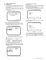
FLOW CHART NO.2
Operation is possible from the remote control unit.
Check AL+3.3V line and service it if defective.
No
Replace the remote control receiver(RS101)
or the remote control unit.
Yes
Replace Digital Main PWB Unit.
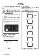
When pressing each switches (SW104~SW109,
SW951~SW953) do the voltage of Pin(29) of CN302
and Pin(2) of CN303 increase?
Yes
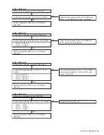
The key operation is not functioning.
FLOW CHART NO.1
Are the contact point and installation state of the key
switches (SW104~SW109, SW951~SW953) normal?
Re-install the switches (SW104~SW109,
SW951~SW953) correctly or replace the poor switch.
Check the switches (SW104~SW109,
SW951~SW953) and their periphery, and service it
if defective.
Yes
Replace Digital Main PWB Unit.
No
No
No operation is possible from the remote control unit.
Picture does not appear normally.(Video input)
FLOW CHART NO.3
Are the video signal inputted to Pin(4) of CN302?
Yes
Check the line between Pin(4) of CN302 and
JK752, and service it if defective.
No
Replace Digital Main PWB Unit or LCD Module
Assembly.
Содержание LT19D200 - 19" LCD TV
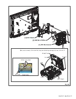
Страница 10: ...1 10 No YA711 Rev 002 2 Rear Cabinet S 1 1 Stand Assembly S 2 S 4 S 2 S 2 S 3 Fig D1 ...
Страница 70: ...2 54 No YA711 Rev 001 No YA711 Rev 001 2 53 TOP PATTERN DIAGRAMS MAIN PWB PATTERN SOLDER SIDE ...
Страница 71: ... No YA711 Rev 001 2 55 2 56 No YA711 Rev 001 R699 TOP MAIN PWB PATTERN PARTS SIDE ...


