1-8 (No.YA379)
SECTION 3
DISASSEMBLY
3.1
DISASSEMBLY PROCEDURE
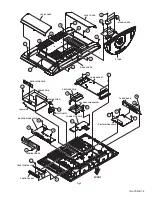
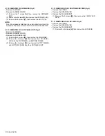
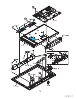
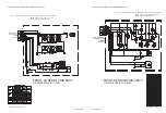
3.1.1 REMOVING THE STAND (Fig.1)
(1) Remove the 2 screws
[A]
, then remove the STAND
COVER.
(2) Remove the 4 screws
[B]
, then remove the STAND.
3.1.2 REMOVING THE REAR COVER (Fig.1)
• Remove the STAND.
(1) Remove the JACK COVER (L/R).
(2) Remove the 7 screws
[C]
, the 4 screws
[D]
, and the 1
screw
[E]
.
(3) Remove the REAR COVER.
3.1.3 REMOVING THE REGULATOR PWB (Fig.1)
• Remove the STAND.
• Remove the REAR COVER.
(1) Remove the 4 screws
[F]
, then remove the FAN
BRACKET.
(2) Remove the 1 screw
[G]
, then remove the POWER CORD
HOLDER.
(3) Remove the POWER CORD from the POWER PWB.
(4) Remove the REGULATOR PWB.
3.1.4 REMOVING THE POWER PWB (Fig.1)
• Remove the STAND.
• Remove the REAR COVER.
• Remove the FAN BRACKET.
(1) Remove the 5 screw
[H]
, then remove the POWER PWB.
3.1.5 REMOVING THE ANALOG SYGNAL PWB (Fig.1)
• Remove the STAND.
• Remove the REAR COVER.
• Remove the FAN BRACKET.
(1) Remove the 6 screws
[J]
, then remove the TERMINAL
BASE.
(2) Remove the 5 screws
[K]
, then remove the ANALOG
SIGNAL PWB.
3.1.6 REMOVING THE FRONT CONTROL PWB (Fig.1)
• Remove the STAND.
• Remove the REAR COVER.
(1) Remove the 3 screws
[L]
, then remove the CONTROL
ASSY with the FRONT CONTROL PWB.
(2) Remove the FRONT CONTROL PWB.
3.1.7 REMOVING THE RECEIVER PWB (Fig.1)
• Remove the STAND.
• Remove the REAR COVER.
(1) Remove the 3 screws
[M]
and the 1 screw
[N]
, then
remove the TUNER BASE.
(2) Remove the 4 screws
[P]
, then remove the RECEIVER PWB.
3.1.8 REMOVING THE CONNECTOR PWB (Fig.1)
• Remove the STAND.
• Remove the REAR COVER.
(1) Remove the 4 screws
[R]
, then remove the RECEIVER
PWB BRACKET.
(2) Remove the 1 screw
[S]
, then remove the CONNECTOR PWB.
3.1.9 REMOVING THE DIGITAL SIGNAL PWB (Fig.1)
• Remove the STAND.
• Remove the REAR COVER.
• Remove the TUNER BASE.
(1) Remove the 5 screws
[T]
, then remove the DIGITAL
SIGNALPWB.


