


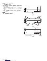


1-12 (No.MA069)
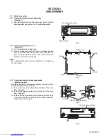
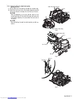
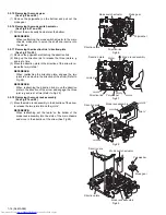
3.2.5 Removing the pinch arm (F) assembly
(See Fig.11 and 12)
(1) Remove the polywasher and pull out the pinch arm
(F)
as-
sembly.
(2) Remove the compulsion spring.
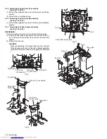
3.2.6 Removing the pinch arm (R) assembly
(See Fig.11 and 12)
(1) Remove the polywasher and pull out the pinch arm
(R)
as-
sembly.
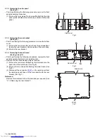
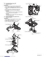
3.2.7 Removing the slide chassis assembly
(See Fig.13 and 14)
REFERENCE:
It is not necessary to remove the head and the tape guide.
(1) Move the slide chassis assembly in the direction of the ar-
row to release the two joints
l
and remove from the main
chassis.
(2) Remove the rack link.
CAUTION:
When reassembling, first reattach the rack link, and next
fit the boss
m
and hook
n
of the slide chassis assembly
to the hole of the main chassis, and engage the two joints
l
.
Fig.11
Fig.12
Fig.13
Fig.14
Polywasher
Polywasher
Pinch arm
(F) assembly
Pinch arm
(R) assembly
Polywasher
Pinch arm (F) assembly
Compulsion
spring
Pinch arm
(R) assembly
Polywasher
Slide chassis assembly
Joint l
Joint l
Boss m
Hook n
Rack link
Head
Tape guide
Содержание KS-T707
Страница 25: ... No MA069 1 25 ...
Страница 43: ...3 7 Grease point 1 2 FG 84M CFD 409 EP 56 SW 474B SW 902 MEN 223 MEA 512R CFD 250H 1 2 3 5 6 4 ...
Страница 44: ...3 8 Grease point 2 2 11 12 7 21 24 27 28 46 44 41 62 33 35 13 10 42 39 ...
Страница 49: ...3 13 MEMO ...