background image

2-6

I

H

A

B

C

D

E

F

G

1

2

3

4

5

6

KS-FX8R

KS-FX8R

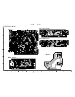
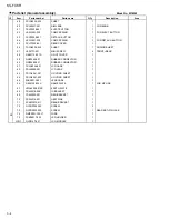
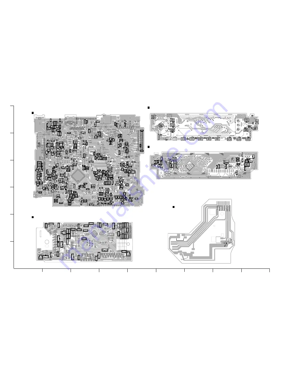
Printed circuit boards

BZ841

C1

C2

C3

C4

C5

C6

C7

C8

C9

C31

C32

C33

C41

C42

C43

C51

C52

C53

C54

C55

C71

C72

C73

C74

C75

C76

C77

C81

C82

C83

C84

C161

C162

C163

C164

C165

C166

C167

C168

C169

C170

C171

C172

C173

C174

C175

C176

C177

C178

C179

C180

C181

C182

C183

C184

C241

C242

C243

C244

C301

C302

C303

C304

C305

C306

C307

C313

C314

C315

C321

C322

C701

C702

C703

C704

C705

C706

C707

C708

C709

C710

C711

C781

C782

C801

C841

C881

C882

C891

C901

C902

C903

C904

C905

C906

C907

C908

C909

C981

CJ601

CP401

CP901

D1

D2

B902

D5

D6

D161

B948

B950

D321

D322

D781

D782

D783

D891

D901

D902

D981

D982

IC71

IC161

IC301

IC701

IC801

IC901

J1

J321

J801

L1

L902

L903

PL701

Q1

Q2

Q3

Q4

Q5

Q6

Q7

Q8

Q9

C982

Q31

Q32

Q41

Q42

Q51

Q52

Q241

Q321

Q331

Q341

Q351

Q781

Q782

Q784

Q841

Q881

Q891

Q901

B927

Q903

Q904

Q976

Q977

R1

R2

R3

R4

R5

R6

R8

R9

R10

R11

R12

R31

R32

R33

R34

R41

R42

R43

R44

B915

R53

R54

R55

R56

R57

R58

R59

R71

R72

R73

R81

R82

R83

R84

R161

R163

R162

R164

R165

R166

R167

R168

R169

R170

R171

R172

R173

R241

R242

R243

R244

R245

R246

R247

R301

R302

R303

R304

R305

R311

R312

R313

R314

R321

R322

R323

R331

R332

R333

R341

R342

R343

R351

R352

R353

R701

R702

R703

R704

R705

R706

R707

R708

R711

R712

R713

B802

R715

R716

R717

R718

R719

R720

R721

R722

R723

R724

R725

R726

R727

R728

R729

R730

R731

R732

R733

R734

R735

R736

R737

R738

R739

R740

R741

R742

R743

R744

R745

R781

R782

R801

R802

R803

R804

R805

R806

R807

R808

R809

R810

R841

R842

R881

R882

R891

R892

R901

R902

R903

R904

R905

R906

R907

R908

R909

R976

R977

R978

S701

S702

TU1

X71

X701

L901

R306

B815

B955

B936

B951

B946

Q902

B949

B812

B933

B947

B919

C712

B937

B945

B901

B903

B905

B810

B932

B911

B801

B954

B906

B907

B908

B910

B803

B916

B805

B920

R746

R747

B913

B914

D701

D702

D703

D704

D709

D705

D706

D707

D708

D710

B808

B935

B809

B940

B943

B912

B917

B807

D242

B944

B939

B938

B934

B930

B814

B931

D241

Q53

B921

B923

B924

R714

B922

B925

B806

R60

D3

B904

B811

B942

B929

B926

B941

Q10

D4

R307

Q701

R748

B813

B928

R308

C713

B952

R309

B816

C910

C318

C309

C308

C319

B817

B818

B819

B820

C911

C714

17

18

1

1

1

2

1

1

2

3

4

5

6

7

8

1

15

10

20

1

14

1

2

3

4

8

19

16

1

15

7

11

14

1

2

FSMW1091A

RL

FL

TP01

TP02

L-CH

R-CH

13

9

10

5

1

16

12

T03

Printed circuit boards

Main board

Mecha control board

C401

C402

C403

C404

C405

C406

C407

C408

C409

C410

C411

C412

C413

C414

C416

C417

C418

C419

C421

C422

C423

C424

C425

CJ401

B405

B403

D401

D402

IC402

Q401

Q402

Q403

R401

R402

R403

R404

R405

R406

R407

R408

R410

R411

R412

R413

R414

R415

R416

R417

R418

R420

B413

R422

R423

R424

R425

R426

VR401

VR402

IC401

CJ403

B412

B407

B401

B408

B410

B406

B409

B404

B402

B411

1

2

1

2

1

11

21

31

1

FSMW1093A

1

T02

CA-IN

Main:-
Main:+
 Sub:-
 Sub:+

CrO2

S T- B Y

3

MODE

M

J

CA-IN

Main+

Sub+

MODE

Pho- T

r

CrO2

Main

Sub

St.BY

D

.Gnd

Anode

Reel board

D601

D602

D603

D604

D605

D606

D607

D608

D609

D610

D611

D612

D613

D614

D615

D616

D617

D618

D619

D620

D621

D622

D623

D624

D625

D626

D627

D641

D642

D643

EN601

IC602

R601

R602

R604

R605

R607

R608

R609

R610

S601

S602

S603

S604

S605

S606

S607

S608

S609

S610

S611

S612

S613

S614

S615

S616

S617

S618

S619

LCD1

S01

D658

C601

C602

C603

C604

C605

C606

CN601

D641

D642

D643

D651

D652

D653

D654

D655

D656

D657

IC601

Q641

Q642

R603

R606

R611

R612

R613

R614

R615

R616

R620

R621

R622

R623

R624

R625

R626

R627

R628

R629

R630

R641

R642

R643

R644

R645

R646

R650

R651

R652

R653

R654

R655

R656

R657

R658

R661

R662

R663

R669

R670

R671

1

1

20

21

40

41

60

80

61

T01

FSMW1081-001QX

Front board (Foerward side)

Front board (Reverse side)

Содержание KS-FX8R

Страница 1: ...Y OF JAPAN LTD KS FX8R KS FX8R Area Suffix E Continental Europe 40Wx4 TP DISP RPT SSM SCM MO RND 7 8 9 10 11 12 PTY CD CH FM AM TAPE I ATT DOLBY B NR DAB RDS KS FX8R KS FX8R Contents Safety precaution Disassembly method Adjustment method Description of major ICs 1 2 1 3 1 10 1 14 ...

Страница 2: ...KS FX8R 1 2 Burrs formed during molding may be left over on some parts of the chassis Therefore pay attention to such burrs in the case of preforming repair of this system Safety precaution ...

Страница 3: ...on the left side of the front chassis two joints b on the right side and one joint c from upside then detach the front chassis toward the front side 1 2 Removing the front chassis See Fig 2 3 Remove the three screws B attaching the heat sink on the left side of the body and remove the heat sink 1 Removing the heat sink See Fig 4 Joint c Heat sink Fig 2 Fig 1 Fig 3 Fig 4 Front panel unit Front chas...

Страница 4: ...tom cover Remove the five screws C attaching the rear panel and one screw D attaching the pine jack on the back of the body 1 Removing the rear panel See Fig 6 Prior to performing the following procedure remove the front chassis the heat sink bottom cover and the rear panel Remove the two screws E attaching the main amplifier board assembly on the top cover Disconnect connector CP401 on the main a...

Страница 5: ... the top cover 1 Removing the cassette mechanism assembly See Fig 8 Remove the front panel unit from the main body Remove the five screws G attaching the rear cover on the back of the front panel unit Remove the control switch board from the front panel unit 1 2 3 Removing the LCD key control switch board See Fig 9 and 10 Cassette mechanism assembly F F F Top cover Fig 8 G G G G Fig 9 Fig 10 LCD K...

Страница 6: ...ection of the arrow 1 2 3 4 Removal of the cassette mechanism Removing the head amplifier board See Fig 1 and 2 Disconnect the 6pin wire from connector CN402 and the card wire from CN403 on the head amplifier board Refer to Fig 1 and 2 Remove the four screws B on the bottom of the cassette mechanism 1 2 Removing the cassette mechanism assembly See Fig 1 to 3 Fig 1 Cassette mechanism ass y Head rel...

Страница 7: ... the one side of the sub chassis Then release the sub chassis from the tab f Removing the sub chassis See Fig 6 Prior to performing the following procedure remove the head relay board the load arm and the sub chassis Remove the screw E attaching the reinforce bracket Remove the reinforce bracket Push the tab g fixing the cassette holder in the direction of the arrow and open the cassette holder an...

Страница 8: ...lay board the load arm the sub chassis the cassette holder and the holder arm Disengage the part n inside of the reel driver which engages with the shaft using a pincette or something like that Then remove the reel driver from the shaft Remove the reel driver spring and the reel table Removing the reel disc ass y I See Fig 12 to 14 When reassembling make sure to use a new slit washer ATTENTION Fig...

Страница 9: ...ve the reel disc ass y II as with the reel disc ass y I 1 2 3 Removing the reel disc ass y II See Fig 12 to 15 Do not break the front panel tab fitted to the metal cover ATTENTION Prior to performing the following procedure remove the reel disc I ATTENTION Fig 15 Push aside the gear and reattach the reel disc Ass y I Reel disc ass y II ...

Страница 10: ...nism adjustment Measuring conditions Amplifier section Power supply voltage DC14 4V 10 5 16V Load impedance 4 2Speakers connection Line out 20k Standard volume position Balance and Bass Treble volume Fader Center Indication 0 Loudness Dolby NR Sound Cruise Off Volume position is about 2V at speaker output with following conditions Playback the test tape VT721 AM mode 999kHz 62dB INT 400Hz 30 modul...

Страница 11: ...th screw Fixed screw Height adjusting screw c Height adjusting screw b Height adjusting screw a Arrangement of adjusting test points Head section view Cassette mechanism Surface Tape speed adjust Motor assembly Playback head Azimuth screw ...

Страница 12: ...s type of extension cord is needed to check operation of the mechanism assembly after disassembly 3 Extension cord EXTKSRT002 6P 6 pin extension cord For connection between mechanism assembly and main board assembly Check for mechanism driving section such as motor etc Disassembly method 1 Remove the bottom cover 2 Remove the front panel assembly 3 Remove the top cover 4 Install the front panel 5 ...

Страница 13: ... b In this case the phase difference should be within 45 3 Engage the reverse mode and adjust the output level to maximum with azimuth adjustment screw c The phase difference should be 45_Kor more 4 When switching between forward and reverse modes the difference between channels should be within 3dB Between FWD Lch and Rch REV Lch and Rch 5 When the test tape VT721 315Hz is played back the level d...

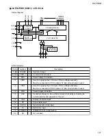
Страница 14: ... driver I O selector output for J BUS H OUT L INPUT Non connect J BUS Data input J BUS Data output J BUS Clock in output Non connect Non connect Non connect Non connect Non connect Non connect Port GND Port Vdd Non connect AF check output L AF check Monaural on off selecting output H mono on FM AM switching output L FM H AM Auto seek stop selecting output H Seek L Stop Pulse signal input port for ...

Страница 15: ...tion data output I2C information clock input Non connect Non connect Non connect Non connect Non connect Non connect Non connect Non connect Non connect Non connect Non connect Non connect Mute output Power ON OFF switching output H power on Non connect Non connect Non connect Non connect Non connect CPU power supply STOP signal output terminal Clock input for RDS RDS data input Remocom input Deta...

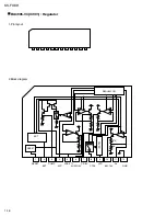
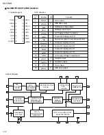
Страница 16: ...16 BA4905 V3 IC901 Regulator 1 Pin layout 2 Block diagram 1 2 3 4 5 6 7 8 9 10 11 12 EXT EXT ACC AUDIO 9V CTRL ILM 10V GND RESET RESET COMP VDD 5 7V CD 8V VCC AJ 1 2 3 4 5 6 7 8 9 10 11 12 37K 5K REGULATOR OIVPC ...

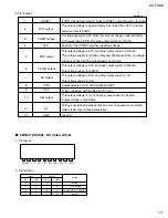
Страница 17: ...and max output current is 500mA This voltage supply for AUDIO This output voltage is 8 0V and max output current is 1A This voltage supply for CD Output selector of CD AUDIO ILM and EXT To be connected with the BACK UP of car This output voltage is 10V and max output current is 500mA Output voltage is adjustable Putting a resistance between ILM and AJ or between AJ and GND makes ILM output voltage...

Страница 18: ...BREF PBFIN1 PBGND PBRIN1 PBFB1 I O O I I I O O I I I Resistance for setting the reference Ground TAPE input Output reference Playback equalizer amplifier output Playback equalizer amplifier capacitance Playback equalizer amplifier feedback Playback equalizer amplifier input Playback equalizer amplifier ground Playback equalizer amplifier input Center Playback equalizer amplifier reference Playback...

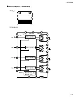
Страница 19: ... 1 Pin layout 2 Block diagram IN1 IN2 IN3 IN4 STBY 2 1 11 13 23 10 TAB PROTECTOR ASO SURGE TSD INPUTBUFFER1 INPUTBUFFER2 INPUTBUFFER3 INPUTBUFFER4 AMP1 AMP2 AMP3 AMP4 MUTE PVCC1 PVCC2 INVCC 12 22 14 18 6 3 4 5 7 8 9 15 16 17 19 20 21 1 23 ...

Страница 20: ... 1Y 2Y 2Y 3Y 4Y Output Output Output Output Sample as Load Circuit 1 Sample as Load Circuit 1 Sample as Load Circuit 1 1k 1k S1 CL Input Outout C L H H A X L H Y Z H L 1 2 3 4 5 6 7 14 13 12 11 10 9 8 HD74HC126FP X IC801 Buffer 1 Pin layout 3 Block diagram 2 Pin function ...

Страница 21: ...Must be connected to VDD1 when a 1 2 bias drive scheme in used Power supply connection Oscillator connection An oscillator circuit is formed by connecting an external resistor and capacitor to this pin Display off control input Chip enable input Synchronization clock input Serial data input DIMMER Control signal output Non connect O O I I I O I I I I O Pin No Symbol Description I O 2 Pin Functions...

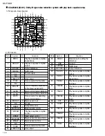
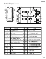
Страница 22: ...ref MUX VDDA GND CIN SCOUT RDCL T75 OSCO OSC1 VDD GND TEST MODE 1 2 3 4 5 6 7 8 16 15 14 13 12 11 10 9 QUAL RDDA Vref MUX VDDA GND CIN SCOUT MODE TEST GND VDD OSC1 OSC0 T75 RDCL O O I I O I O O 1 2 3 4 5 6 7 8 9 10 11 12 13 14 15 16 Non connect RDS data output Reference voltage output Multiplex signal input 5V Supply voltage for analog Ground for analog part 0V Sub carrier output of reconstruction...

Страница 23: ...E ICL IMO IBL IAL Serial data input output Ground output left rear output left front Treble control capacitor left channel or input from an external equalizer Bass control capacitor left channel or output to an external equalizer Bass control capacitor left channel Input volume 1 left control part Input loudness left control part Output source selector left channel Not used Not used Input C left s...

Страница 24: ...KS FX8R Printed in Japan 200101 O VICTOR COMPANY OF JAPAN LIMITED MOBILE ELECTRONICS DIVISION PERSONAL MOBILE NETWORK BUSINESS UNIT 10 1 1Chome Ohwatari machi Maebashi city Japan No 49850 ...

Страница 25: ...ECTOR IC701 CPU IC751 JVC BUS TU_L TU_R SK ST SM MONO SD ST SEEK STOP FMOSC AFCK FMEO AMEO FM AM RDSCK RDSDA TAPE L TAPE R F R TAPEIN MOTOR T MUTE ENC1 ENC2 KEY0 KEY1 KEY2 LCDCE LCDDA LCDCK REMOCON MUX SCL SDA FL FR RL RR FLOUT FROUT RLOUT RROUT LINE OUTPUT REARL REARR CH_L CH_R SCK SI SO J751 JBUSSI JBUSSO JBUSIO JBUSSCK CJ902 CP902 MOTOR MUTE SW PB HEAD IC901 HEAD AMP CN901 L CH R CH CJ901 ...

Страница 26: ...2 2 KS FX8R M E M O ...

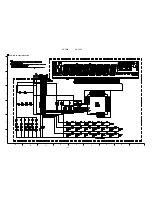
Страница 27: ... 2 3 4 5 6 Standard schematic diagrams Main amp section Parts are safety assurance parts When replacing those parts make sure to use the specified one TUNER SIGNAL TAPE SIGNAL CD CH SIGNAL FRONT SIGNAL REAR SIGNAL Main amp section g ...

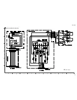
Страница 28: ...2 4 I H A B C D E F G 1 2 3 4 5 6 KS FX8R KS FX8R LCD Key control section ...

Страница 29: ...2 5 KS FX8R I H A B C D E F G 1 2 3 4 5 6 TAPE SIGNAL Mecha control Head amp section ...

Страница 30: ... B945 B901 B903 B905 B810 B932 B911 B801 B954 B906 B907 B908 B910 B803 B916 B805 B920 R746 R747 B913 B914 D701 D702 D703 D704 D709 D705 D706 D707 D708 D710 B808 B935 B809 B940 B943 B912 B917 B807 D242 B944 B939 B938 B934 B930 B814 B931 D241 Q53 B921 B923 B924 R714 B922 B925 B806 R60 D3 B904 B811 B942 B929 B926 B941 Q10 D4 R307 Q701 R748 B813 B928 R308 C713 B952 R309 B816 C910 C318 C309 C308 C319 B...

Страница 31: ...lies are not available as service parts Contents Exploded view of general assembly and parts list Cassette mechanism assembly and parts list Electrical parts list Packing materials and accessories parts list KS FX8R 3 2 3 5 3 10 3 14 Area suffix E Continental Europe ...

Страница 32: ... board Mecha control board Front board 7 4 11 11 11 11 5 6 6 6 6 2 1 3 38 37 42 51 52 75 45 46 39 40 41 53 54 58 43 44 48 49 47 50 57 57 57 55 56 61 LCD1 60 64 59 63 62 65 10 9 66 29 22 19 15 16 32 24 36 35 17 18 21 33 28 23 34 20 14 14 26 31 27 30 25 67 12 8 12 68 74 69 70 13 13 71 72 72 73 ...

Страница 33: ...KS3798 002 RELEASE LEVER 1 23 VKS3793 001 LOCK LEVER TOP 1 24 VKS3794 003 LOCK LEVER L 1 25 VKS3795 002 LOCK LEVER R 1 26 VKS5563 001 GEAR 1 27 VKZ4786 002 OIL DAMPER 1 28 FSKW4012 002 T SPRING 1 FOR L LEVER TOP 29 VKW5264 005 T SPRING 1 FOR RELEASE LEVER 30 VKW5262 001 T SPRING 1 FOR L LEVER R 31 QYSDSF2006M SCREW 1 DAMPER L LEVER R 32 VKW5263 002 T SPRING 1 FOR L LEVER L 33 VKZ4777 001 MINI SCRE...

Страница 34: ...INI SCREW 5 FRONT REAR 58 GE40112 001A LIGHT COVER 1 59 QNZ0449 001 RUBBER CONNECTOR 1 60 QNZ0450 001 RUBBER CONNECTOR 1 61 FSYH3024 001 LCD CASE 1 62 FSJK3028 001 LCD LENS 1 63 FSYH4061 001 LIGHTING SHEET 1 64 FSYH4061 002 LIGHTING SHEET 1 65 FSKS3013 001 LENS CASE 1 66 GE30135 002A NAME PLATE 1 FOR MP USE 67 VMA4652 001SS EARTH PLATE 1 68 FSKL4018 00B IC BRACKET 1 69 FSKL4023 001 REG BRACKET 1 7...

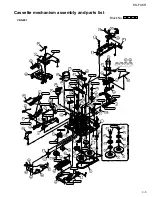
Страница 35: ... 409 49 40 66 75 17 94 93 95 96 16 5 50 28 CFD 409 4 63 64 LEN 315Y2 LEN 315Y2 27 67 25 SW 522B SW 522B 117 CFD 409 LEN 315Y2 107 48 30 3 FG 84M FG 84M 12 108 46 FG 84M FG 84M FG 84M FG 84M 44 34 55 SW 522B 21 38 114 22 33 111 85 82 84 86 71 113 43 110 113 32 111 51 61 37 74 35 60 36 72 9 13 FG 84M FG 84M CFD 409 106 87 45 1 106 Cassette mechanism assembly and parts list Block No M M M 2 CDS 801 ...

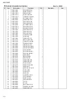
Страница 36: ...CT CAM PLATE 1 28 1 0801 1012S CASSETTE HOLDER 1 30 1 0801 1020S REINFORCE BRKT 1 32 1 0101 2056S IDLE PULLEY A1 1 33 1 0801 2004S REDUCTION GEARA 1 34 1 0801 2005S REDUCTION GEARB 1 35 1 0801 2006S SPG HOLDER F 1 36 1 0801 2007S FRICTION GEARPL 1 37 1 0801 2008S FRICTION GEARFF 1 38 1 0801 2009S MODE GEAR 1 39 1 0801 2010S REEL SPINDLE 2 40 1 0801 2011S REEL DRIVER 2 41 1 0801 2014S GEAR BASE ARM...

Страница 37: ...009 0S M MOTOR WIRE 1 BLACK 94 10801 7009 1S M MOTOR WIRE 1 RED 95 10801 7010 0S S MOTOR WIRE 1 ORANGE 96 10801 7010 1S S MOTOR WIRE 1 BROWN 97 10801 7015 0S HEAD WIRE BLACK 1 98 10801 7015 1S HEAD WIRE BROWN 1 99 10801 7015 2S HEAD WIRE RED 1 100 10801 7015 3S HEAD WIRE ORANG 1 101 10801 7015 4S HEAD WIRE YELLO 1 102 10801 7015 5S HEAD WIRE WHITE 1 103 1 0801 7016S HEAD PCB 1 104 1 0801 7025S CON...

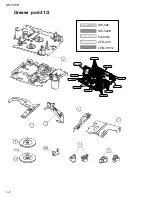
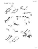
Страница 38: ...3 8 KS FX8R SW 902 SW 522B FG 84M CFD 409 LEN 315Y2 Grease point 1 2 FG 84M FG 84M SW 902 SW 902 FG 84M FG 84M SW 902 FG 84M FG 84M SW 902 SW 902 ...

Страница 39: ...3 9 KS FX8R Grease point 2 2 ...

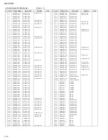
Страница 40: ...X C CAPACITOR C 244 QERF1HM 224Z E CAPACITOR 0 22MF 20 50V C 301 QERF1CM 106Z E CAPACITOR 10MF 20 16V C 302 QERF1CM 106Z E CAPACITOR 10MF 20 16V C 303 NCS21HJ 471X C CAPACITOR C 304 NCS21HJ 471X C CAPACITOR C 305 NCB21EK 104X C CAPACITOR C 306 NCB21EK 104X C CAPACITOR C 307 QERF1HM 475Z E CAPACITOR 4 7MF 20 50V C 308 QERF1HM 225Z E CAPACITOR 2 2MF 20 50V C 309 QERF1HM 225Z E CAPACITOR 2 2MF 20 50V...

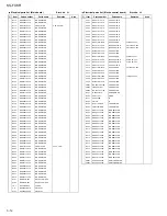
Страница 41: ...4 NRSA02J 102X MG RESISTOR R 41 NRSA02J 152X MG RESISTOR R 42 NRSA02J 102X MG RESISTOR R 43 NRSA02J 103X MG RESISTOR R 44 NRS181J 102X MG RESISTOR R 53 NRSA02J 473X MG RESISTOR R 54 NRSA02J 473X MG RESISTOR R 55 NRSA02J 103X MG RESISTOR R 56 NRSA02J 222X MG RESISTOR R 57 NRSA02J 103X MG RESISTOR R 58 NRSA02J 153X MG RESISTOR R 59 NRSA02J 471X MG RESISTOR R 60 NRSA02J 473X MG RESISTOR R 71 NRS181J ...

Страница 42: ...NRSA02J 104X MG RESISTOR R 977 NRSA02J 273X MG RESISTOR R 978 NRS181J 123X MG RESISTOR S 701 QSW0451 001 DETECT SWITCH S 702 QSW0451 001 DETECT SWITCH TU 1 QAU0156 002 TUNER X 71 QAX0263 001Z CRYSTAL X 701 QAX0406 002Z CRYSTAL Item Parts number Parts name Area Electrical parts list Mecha control board Remarks Block No 02 A C 401 NDC21HJ 101X C CAPACITOR C 402 NDC21HJ 101X C CAPACITOR C 403 NDC21HJ...

Страница 43: ...2X MG RESISTOR R 609 NRSA02J 182X MG RESISTOR R 610 NRSA02J 272X MG RESISTOR R 611 NRSA02J 392X MG RESISTOR R 612 NRSA02J 821X MG RESISTOR R 613 NRSA02J 821X MG RESISTOR R 614 NRSA02J 122X MG RESISTOR R 615 NRSA02J 182X MG RESISTOR R 616 NRSA02J 272X MG RESISTOR R 620 NRS181J 561X MG RESISTOR R 621 NRS181J 271X MG RESISTOR R 622 NRS181J 271X MG RESISTOR R 623 NRS181J 271X MG RESISTOR R 624 NRS181J...

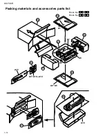
Страница 44: ...3 14 KS FX8R Packing materials and accessories parts list Block No M M M 3 Block No M M M 4 A1 P2 P4 A15 KIT A10 A14 P7 P6 A16 A2 A6 P2 P5 P3 A9 P1 A7 A8 P5 ...

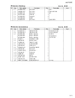
Страница 45: ...CTIONS 1 A 2 GET0006 002A INSTRUCTIONS 1 A 3 GET0006 005A INSTALL MANUAL 1 GET0006 003A INSTALL MANUAL 1 GET0006 004A INSTALL MANUAL 1 A 4 BT 54013 1 WARRANTY CARD 1 A 5 VND3046 001 SERIAL TICKET 1 A 6 VND3050 002 IDENTITY CARD 1 A 7 LV40978 001A CAUTION SHEET 1 A 8 FSJD2034 001 TRIM PLATE 1 A 9 FSKM2004 202 MOUNTING SLEEVE 1 A 10 VKZ4027 202 PLUG NUT 1 A 11 VKH4871 001SS MOUNT BOLT 1 A 12 VKZ4328...

Отзывы: