

KS-F383R,KS-F380R
(No.49813)1-5
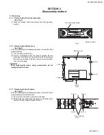
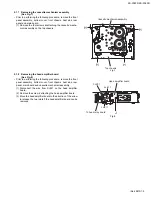
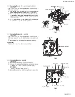
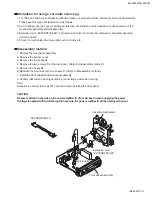
2.1.7 Removing the cassette mechanism assembly
(See Fig.7)
• Prior to performing the following procedure, remove the front
panel assembly, bottom cover, front chassis, heat sink, rear
panel and main board.
(1) Remove the four screws
H
attaching the cassette mecha-
nism assembly on the top chassis.
Fig.7
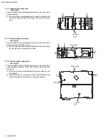
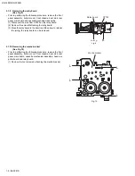
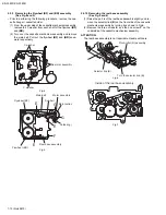
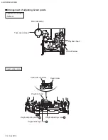
2.1.8 Removing the head amplifier board
(See Fig.8)
• Prior to performing the following procedure, remove the front
panel assembly, bottom cover, front chassis, heat sink, rear
panel, main board and cassette mechanism assembly.
(1) Disconnect the wire from CJ901 on the head amplifier
board.
(2) Remove the screw
J
attaching the head amplifier board.
(3) Move the head amplifier board in the direction of the arrow
to release the two joints
f
, the head amplifier board can be
removed.
Fig.8
H
H
H
H
Top chassis
Cassette mechanism assembly
Joint f
J
CJ901
Head amplifier board
To head relay board
Joint f
Содержание KS-F380R
Страница 25: ...KS F383R KS F380R No 49813 1 25 ...
Страница 35: ...KS F383R KS F380R M E M O ...
Страница 45: ...KS F383R KS F380R 3 9 Grease point 2 2 12 35 5 30 20 19 3 16 38 42 43 4 39 37 15 ...


