
2
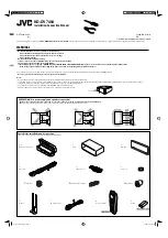
INSTALLATION (IN-DASH MOUNTING)
The following illustration shows a typical installation. If you have any questions or require information regarding installation kits, consult your JVC car audio dealer or a company supplying kits.
• Make sure not to block the fan on the rear to maintain proper ventilation when installing the unit.
• If you are not sure how to install this unit correctly, have it installed by a qualified technician.
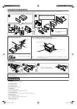
Removing the unit
Before removing the unit, release the rear section.
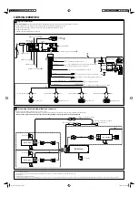
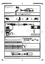
Do the required electrical connections.
Bend the appropriate tabs to hold the
sleeve firmly in place.
*
1
When you stand the unit, be careful not to damage the fuse on the rear.
*
2
Not supplied for this unit.
*
3
Avoid touching the connectors.
When installing the unit without using the sleeve
In a Toyota car for example, first remove the car radio and install the unit in its place.
When using the optional stay
Note
:
When installing the unit on the mounting bracket, make sure to use the 8 mm-long screws. If longer screws
are used, they could damage the unit.
Install the unit at an angle of less than 30˚.
Insert the two handles, then pull them as
illustrated so that the unit can be removed.
Screw (option)
Stay (option)
Fire wall
Dashboard
Bracket
*
2
Flat head screws (M5
×
8 mm)
*
2
Flat head screws (M5
×
8 mm)
*
2
Bracket
*
2
TROUBLESHOOTING
•
The fuse blows.
*
Are the red and black leads connected correctly?
•
Power cannot be turned on.
*
Is the yellow lead connected?
•
No sound from the speakers.
*
Is the speaker output lead short-circuited?
•
Sound is distorted.
*
Is the speaker output lead grounded?
*
Are the “–” terminals of L and R speakers grounded in common?
•
Noise interfere with sounds.
*
Is the rear ground terminal connected to the car’s chassis using shorter and thicker cords?
•
This unit becomes hot.
*
Is the speaker output lead grounded?
*
Are the “–” terminals of L and R speakers grounded in common?
•
This unit does not work at all.
*
Have you reset your unit?
Instal1-2_DV7404[UI]_1.indd 2
Instal1-2_DV7404[UI]_1.indd 2
2/4/08 12:04:17 PM
2/4/08 12:04:17 PM


