background image

2-3

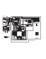
Parts are safety assurance parts.
When replacing those parts make
sure to use the specified one.

CD section

C570

C566

C563

C564

C565

C567

C568

C569

C571

C558

C572

C532

C557

C562

C561

C555

C554

R590

X561

C581

IC541

L572

R547

SFSY

R522

R523

R515

IC571

R504

R511

R512

C556

C533

C534

C535

R532

R5015

C548

C549

C547

C553

C551

C552

R556

C574

R557

ARF

VREF

R524

C591

R580

R525

R526

R527

PO4

PIO1

PIO2

R566

R581

R591

R586

R585

R589

R599

C578

C531

R565

R564

R563

R555

R5002

C560

R595

R596 C592

C550

C582

D501

C559

R553

C580

R593

R583

C584

R546

C594

C538

C576

R584

R531

R554

L571

Q582

Q581

C541

C542

C501

C543

FEI

R548

R551

R549

R550

LRCKI

BCKI

AIN

LRCK

BCK

AOUT1

DOUT

C502

C515

C516

C512

IC501

R519

C519

R560

ZDET

IPF

SBOK

SBSY

PIO3

C518

C511

R518

C504

R521

R520

R503

R502

C514

R505

C503

R513

R514

C513

Q502

R544

C537

C536

C544

C545

R545

IO0

IO1

R582

R592

C505

C546

CN501

C506

R577

R578

C575

Q571

C517

C573

PO5

R528

R552

C520

R597

IC581

R587

R598

R562

C593

R588

RFDC

R568

R543

R541

R542

R5003

R567

R561

C590

C583

C596

C597

L532

L531

C527

C521

C529

C528

C526

C525

C522

C523

C524

0.01

0.1

0.1

68p

0.015

0.1

NBE41AM-476X

0.0047

0.01

0.015

0.1

47p

270P

47/16

47/16

0.1

0.1

0.1

75

QAX0933-001Z

100p

TC94A70FG-005A

47u

4.7k

100

100

6.8k

NJM2878F4-15-X

8.2k

10K

7.5k

0.1

270P

0.027

0.018

220

2.2K

0.1

22/16

47/16

0.01

0.1

0.1

0

0.01

0

150

100p

10

100

100

47K

100

0

0

5.6K

27k

0

0

0.01

0.001

100

100

100

0

1M

0.1

27k

5.6K

150p

0.1

150p

1A3G-T1

47/16

22k

QTE1E57-475Z

QTE1E57-475Z

15K

15K

820p

100k

820p

47/16

5600p

1.5M

3.3K

0

47u

RT1N141C-X

2SA1365/F/-X

0.033

0.033

0.1

5.6k

47k

150k

330k

100/16

0.047

0.047

0.01

LA6242H-X

12K

0.047

100k

0.047

0.01

3K

0.01

1.5k

8.2K

22

22

0.01

5.1k

47/16

3.3k

10k

0.01

2SA1705/ST/-T

100

2200p

0.1

0.1

0.1

100k

1M

1M

0.01

0.1

QGB2027M4-22S

0.01

22

22

100/16

2SA1708/ST/-T

120p

0.033

1k

15k

0.022

10k

NJM4580M-X

10k

10k

10K

QTE0J57-476Z

10k

10K

100

100

10k

220

10K

10K

QTE0J57-476Z

100/16

0.1

47u

47u

0.01

0.1

0.01

100/16

100/16

100/16

100/16

0.1

0.1

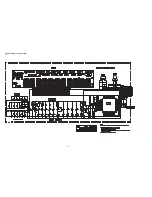
/RST

/RST

RFOK

FMO

BUS0

BUCK

SRAMSTB

FEED-

CDON

/CCE

BUS1

BUS2

BUS3

REQ

VR

PSW

SW2

SW1

CD.L

CD_8V

CD.R

CD.RO

GND

CD.LO

BUS0

BUS1

BUS2

BUS3

LM0

BUCK

/CCE

REQ

FEED-

RFOK

VF2

FEED+

RFVDD

GND

VT2

VF2

FEED+

SW1

1.5_V7

VT1

SRAMSTB

SW2

VF1

VT2

VT1

PSW

VF1

SPINDLE-

VR

SPINDLE-

LD


FOCUS-

VREF

FOCUS+

MD

T
TRACKING-

FEED-

FEED+

SW1

SPINDLE-

SW2

PSW

VCC

TRACKING-

T

FOCUS+

FOCUS-
LD

GND

MD

VR

VF1

VREF

VT1

LD

GND

VT2

VF2

FOCUS-

VREF

FOCUS+

MD

T

TRACKING-

VT2

VT1

MD

9V

VF2

VF1

VDD.5V

AGND

FOO

TRO

CD.RO

FOO

LM0

DMO

TRO

LM1

LD

VREF

SW2

PSW

CD.LO

/RST

SW1

FEED+

FEED-

SPINDLE-

FOCUS+

FOCUS-

TRACKING-

T

LM1

DMO

FMO

!

Содержание KD-BT11E

Страница 1: ...D BT19UR KD BT12E KD BT12EX COPYRIGHT 2008 Victor Company of Japan Limited Lead free solder used in the board material Sn Ag Cu melting point 219 Centigrade Lead free solder used in the board material Sn Cu melting point 230 Centigrade TABLE OF CONTENTS 1 PRECAUTION 1 6 2 SPECIFIC SERVICE INSTRUCTIONS 1 9 3 DISASSEMBLY 1 9 4 ADJUSTMENT 1 25 5 TROUBLESHOOTING 1 26 for E EX EY EU EE for EE for J U U...

Страница 2: ... to 9 kHz 531 kHz to 1 602 kHz FM Tuner Usable Sensitivity 11 3 dBf 1 0 µV 75 Ω 50 dB Quieting Sensitivity 16 3 dBf 1 8 µV 75 Ω Alternate Channel Selectivity 400 kHz 65 dB Frequency Response 40 Hz to 15 000 Hz Stereo Separation 35 dB AM Tuner Sensitivity 20 µV Selectivity 35 dB CD PLAYER SECTION Type Compact disc player Signal Detection System Non contact optical pickup semiconductor laser Number ...

Страница 3: ...M Tuner Usable Sensitivity 11 3 dBf 1 0 µV 75 Ω 50 dB Quieting Sensitivity 16 3 dBf 1 8 µV 75 Ω Alternate Channel Selectivity 400 kHz 65 dB Frequency Response 40 Hz to 15 000 Hz Stereo Separation 30 dB MW Tuner Sensitivity Selectivity 20 µV 35 dB LW Tuner Sensitivity 50 µV CD PLAYER SECTION Type Compact disc player Signal Detection System Non contact optical pickup semiconductor laser Number of Ch...

Страница 4: ...able Sensitivity 11 3 dBf 1 0 µV 75 Ω 50 dB Quieting Sensitivity 16 3 dBf 1 8 µV 75 Ω Alternate Channel Selectivity 400 kHz 65 dB Frequency Response 40 Hz to 15 000 Hz Stereo Separation 30 dB MW Tuner Sensitivity Selectivity 20 µV 35 dB LW Tuner Sensitivity 50 µV CD PLAYER SECTION Type Compact disc player Signal Detection System Non contact optical pickup semiconductor laser Number of Channels 2 c...

Страница 5: ...2 kHz FM Tuner Usable Sensitivity 11 3 dBf 1 0 µV 75 Ω 50 dB Quieting Sensitivity 16 3 dBf 1 8 µV 75 Ω Alternate Channel Selectivity 400 kHz 65 dB Frequency Response 40 Hz to 15 000 Hz Stereo Separation 35 dB AM Tuner Sensitivity 20 µV Selectivity 35 dB CD PLAYER SECTION Type Compact disc player Signal Detection System Non contact optical pickup semiconductor laser Number of Channels 2 channels st...

Страница 6: ...rrs formed during molding may be left over on some parts of the chassis Therefore pay attention to such burrs in the case of preforming repair of this system Please use enough caution not to see the beam directly or touch it in case of an adjustment or operation check ...

Страница 7: ...r diode in the optical pickup The tester s internal power source can easily destroy the laser diode 1 3 Handling the traverse unit optical pickup 1 Do not subject the traverse unit optical pickup to strong shocks as it is a sensitive complex unit 2 Cut off the shorted part of the flexible cable using nippers etc after replacing the optical pickup For specific details refer to the replacement proce...

Страница 8: ...duct uses visible and or invisible laser radiation and is equipped with safety switches which prevent emission of radiation when the drawer is open and the safety interlocks have failed or are defeated It is dangerous to defeat the safety switches 5 CAUTION If safety switches malfunction the laser is able to function 6 CAUTION Use of controls adjustments or performance of procedures other than tho...

Страница 9: ... 1 1 Removing the FRONT CHASSIS assembly See Fig 1 1 Disengage the four hooks a engaged the both side of the FRONT CHASSIS assembly Fig 1 3 1 2 Removing the HEAT SINK See Fig 2 3 1 Remove the three screws A and the two screws B attaching the HEAT SINK See Fig 2 2 Remove the two screws C and the one screw D attaching the HEAT SINK See Fig 3 Fig 2 Fig 3 hook a A B C D ...

Страница 10: ...backward Fig 4 3 1 4 Removing the MAIN BOARD assembly See Fig 5 6 1 Remove the two screws F and the one screw G attaching the MAIN BOARD assembly See Fig 5 2 RemovethetwoscrewsH attachingtheMAINBOARDassembly See Fig 6 3 Disconnect the connector CN501 connected to MAIN BOARD assembly and CD MECHANISM assembly See Fig 6 Fig 5 Fig 6 E F G H CN501 ...

Страница 11: ... Remove the three screws J attaching the CD MECHANISM assembly Fig 7 3 1 6 Removing the SWITCH BOARD assembly See Fig 8 1 Remove the VOLUME KNOB 2 Remove the four screws K attaching the REAR COVER 3 Disengage the nine hooks b engaged the REAR COVER Fig 8 J J hook b hook b K K ...

Страница 12: ...Figs 1 and 2 1 From the both side of the CD mechanism assembly re move the four screws A attaching the top cover See Fig 1 2 Lift the front side of the top cover and move the top cover backward to release the two joints a See Figs 1 and 2 Fig 1 Fig 2 A A A a Top cover A a Top cover ...

Страница 13: ... static electricity See Fig 3 1 From the bottom side of the CD mechanism assembly re move the screw C attaching the base board See Figs 3 and 4 2 Solder the short land c on the pickup See Fig 3 3 Disconnect the flexible wire from the connector on the pick up See Fig 3 4 Remove the base board from the joints d of the frame in the direction of the arrow See Figs 3 and 4 Reference Remove the wires fr...

Страница 14: ...Remove the chassis unit from the dampers on the frame in an upward direction See Fig 6 Note Pay attention to misuse and loss of each spring See Fig 5 When reassembling make sure that the three shafts on the underside of the chassis unit are inserted to the dampers certainly See Fig 6 Fig 5 Fig 6 Front suspension spring Rear suspension spring Rear suspension spring Front suspension spring Chassis u...

Страница 15: ...he clamper assembly See Figs 7 and 8 Remove the top cover Move the clamper assembly in the direction of the arrow to re lease the joints f from the chassis unit Fig 7 Fig 8 f f Clamper assembly Chassis unit f f Clamper assembly Chassis unit ...

Страница 16: ...s unit From the bottom side of the chassis unit remove the screw D and take out the loading feed motor assembly in the direction of the arrow Reference Remove the wires from the soldered sections g of the loading feed motor assembly as required Fig 9 D Loading feed motor assembly g Loading feed motor assembly Chassis unit ...

Страница 17: ...d screw holder as required See Fig 12 7 Release the claw k in the direction of the arrow to remove the feed sub holder See Fig 12 3 2 8 Reattaching the pickup See Figs 10 to 13 1 Reattach the feed sub holder to the pickup See Fig 12 2 Reattach the feed screw holder to the pickup using the screw G See Fig 12 3 Reattach the feed screw assembly and pu shaft holder A to the pickup as before See Fig 11...

Страница 18: ... in the direction of the arrow to re move the trigger arm base from the section s in the direc tion of the arrow 4 Remove the trigger arm from the section t Fig 14 3 2 10 Removing the top plate assembly See Fig 15 Remove the top cover base board chassis unit clamper as sembly and trigger arm 1 Remove the screw H attaching the top plate assembly 2 Move the top plate assembly in the direction of the...

Страница 19: ...e link gear L in the direction of the ar row 3 Move the mode switch in the direction of the arrow 1 to re move the sections z of the top plate assembly 4 Move the mode switch in the direction of the arrow 2 and remove the mode switch from the sections aa ab Note When reattaching the link gear L attach it after aligning the hole ac of the link gear L to the hole ac of the link gear R Reference When...

Страница 20: ...elect arm R from the sections ag See Fig 17 5 From the bottom side of the top plate assembly remove the select lock arm spring from the section ah See Fig 18 6 From the top side of the top plate assembly remove the section aj of the select lock arm from the top plate assem bly at first and remove the sections ak am of the select lock arm from the top plate assembly See Fig 18 Note When removing th...

Страница 21: ... the lock arm assembly from the joint at of the cam plate L assembly See Fig 19 5 From the right side of the lock arm assembly remove the loading roller spring L from the section au See Fig 20 6 From the top side of the lock arm assembly remove the loading roller spring R in the direction of the arrow and re move the loading roller assembly See Fig 20 7 Remove the roller guide R HL washer and roll...

Страница 22: ...ar 2 See Fig 22 3 Pull out the change arm See Fig 22 4 Move the change gear plate rivet assembly in the direction of the arrow 2 to remove the section av of the change gear plate rivet assembly from the chassis unit while moving the change lock lever in the direction of the arrow 1 See Fig 23 5 Pull out the change gear 3A and change gear 3B from the change gear plate rivet assembly See Fig 23 Fig ...

Страница 23: ...sembly top plate assembly loading roller assembly and cam plate R 1 Remove the slide hook rivet assembly and trigger rack spring from the chassis unit See Fig 25 2 From the bottom side of the chassis unit pull out the load ing gear 1 See Fig 26 3 Remove the trigger control spring from the sections ay az See Fig 26 4 Take out the trigger rack plate from the chassis unit See Fig 26 Reference When at...

Страница 24: ...ear 2 in the direction of the arrow 2 while pulling the trigger arm in the direction of the arrow 1 and let the pickup move in the direction of the arrow 3 See Fig 28 3 Slide the spindle motor assembly in the direction of the ar row and take out it in an upward direction from the chassis unit See Fig 28 Reference Remove the wires from the soldered sections c on the base board and remove them from ...

Страница 25: ...e and Bass Treble volume lndication 0 Loudness OFF 4 4 Dummy load Exclusive dummy load should be used for AM and FM For FM dummy load there is a loss of 6dB between SSG output and antenna input The loss of 6dB need not be considered sincedirect reading of figures are applied in this working standard 4 5 How to connect the extension cable for adjusting Caution Be sure to attach the heat sink and re...

Страница 26: ... BT11J BK YL RD BL WH GN BK VI VI BK WH BK GN GY BK WH 2 16 1 8 5 7 12 10 3 9 11 GY BK RD BL WH Black Red Blue White GN VI Violet GY Gray YL Yellow Green 4 7 6 5 4 3 2 1 16 15 14 13 12 11 10 9 BK RD NC BL WH WH GN VI GY YL NC NC WH BK GN BK VI BK GY BK 8 OR WH 15 OR WH OR Orange ...

Страница 27: ... Green VI Violet GY Gray YL Yellow BL WH WH BK GN BK VI BK GY BK OR Orange 1 3 5 7 2 4 6 8 VI GY WH GN VI BK GY BK WH BK GN BK 7 RD 16 YL 8 BK 5 BL WH 3 GN 11 GN BK 2 VI 10 VI BK 4 WH 12 WH BK 1 GY 9 GY BK RD RD 7 YL 4 8 5 7 8 1 2 5 3 6 4 RR Rear Right FR FL RL Rear Left Front Right Front Left REMOTE Remote out ACC MEMORY ACC Line GND Memory Backup Battery Ground ACC MEMORY GND REMOTE RL RL RR RR ...

Страница 28: ...I RD GN BK VI BK WH BK GN GY BK WH 16 1 8 7 2 12 10 3 9 11 GY 4 7 6 5 4 3 2 1 16 15 14 13 12 11 10 9 BK RD BL BL WH WH GN VI GY YL NC NC WH BK GN BK VI BK GY BK 8 OR WH BK RD BL WH Black Red Blue White GN Green VI Violet GY Gray YL Yellow OR Orange OR WH 15 5 BL WH 6 BL ...

Страница 29: ... No MA387 Rev 003 1 29 ...

Страница 30: ... No MA387 Rev 003 VPT Printed in Japan Victor Company of Japan Limited Mobile Entertainment Division 10 1 1chome Ohwatari machi Maebashi city 371 8543 Japan ...

Страница 31: ...1 2008 06 Model No KD BT11E KD BT11EE KD BT11EU KD BT11EX KD BT11EY KD BT11J KD BT11U KD BT11UT KD BT11E KD BT11EE KD BT11EU KD BT11EX KD BT11EY KD BT11J KD BT11U KD BT11UT KD BT19UR Cover Illustration ILLUSTRATION ma387_0001 png ILLUSTRATION ma387_0001 png SPECIFICATION 1 J J UR SECTION 5 TROUBLESHOOTING Title Line No MA387 Rev 001 No MA387 Rev 002 Description 5 2 16 PIN CORD DIAGRAM for KD BT11E...

Страница 32: ...MA8056 M X Z DIODE Addition 1 09 01 D301 MA8062 M X Z DIODE Addition 1 09 01 D302 MA8062 M X Z DIODE Addition 1 09 01 D303 MA8062 M X Z DIODE Addition 1 09 01 D304 MA8062 M X Z DIODE Addition 1 09 01 D341 MA111 X SI DIODE Addition 1 09 01 D351 MA111 X SI DIODE Addition 1 09 01 D714 MA8056 M X Z DIODE Addition 1 09 01 D720 MA8062 M X Z DIODE Addition 1 09 01 D721 MA8062 M X Z DIODE Addition 1 09 01...

Страница 33: ... MA387 R002 3 Packing and accessories M3 Part No Symbol or Rev 001 Rev 002 Part Name Description Qty Models M3 A9 GE20235 002A TRIM PLATE Addition 1 09 M3 P8 GE40218 095A MIRAMA SHEET Addition 1 09 ...

Страница 34: ...Victor Company of Japan Limited Mobile Entertainment Business Group Mobile Entertainment Category 10 1 1chome Ohwatari machi Maebashi city 371 8543 Japan MA387 R002 Printed in Japan No MA387 Rev 001 VPT ...

Страница 35: ...11U KD BT11UT KD BT19UR KD BT11E KD BT11EE KD BT11EU KD BT11EX KD BT11EY KD BT11J KD BT11U KD BT11UT KD BT12E KD BT12EX KD BT19UR Cover Illustration ILLUSTRATION ma387_0001 png ILLUSTRATION ma387_0001 png Category Mobile Entertainment Business Group Mobile Entertainment Category Mobile Entertainment Division 0 COVER 1 Lead free solder used in the board material Sn Ag Cu melting point 219 Centigrad...

Страница 36: ...r KD BT11E EX EY EU EE KD BT19UR 5 2 16 PIN CORD DIAGRAM for KD BT11E EX EY EU EE KD BT19UR KD BT12E EX STANDARD SCHEMATIC DIAGRAMS Schematic Diagram Diagram Name No MA387 Rev 002 No MA387 Rev 003 Description Menu LCD Key control section LCD and Key control section Description of Major ICs Diagram Name No MA387 Rev 002 No MA387 Rev 003 Description Menu IC701 UPD78F1167GC1AF UPD78F1167GC1AF xml ...

Страница 37: ...lectrical parts list Main board 01 Part No Symbol or Rev 002 Rev 003 Part Name Description Qty Models 01 IC701 UPD78F1167GC1AF IC PROGRAMED Addition 1 0A 0B Packing and accessories M3 Part No Symbol or Rev 002 Rev 003 Part Name Description Qty Models M3 A1 GET0508 002B INST BOOK Addition 1 0A M3 A1 GET0508 004B INST BOOK Addition 1 0B M3 A2 GET0508 009B INST MANUAL Addition 1 0A M3 A2 GET0508 011B...

Страница 38: ...Victor Company of Japan Limited Mobile Entertainment Division 10 1 1chome Ohwatari machi Maebashi city 371 8543 Japan MA387 R003 Printed in Japan No MA387 Rev 002 VPT ...

Страница 39: ...neral assembly and parts list Block No M1 CD mechanism assembly and parts list Block No MB Electrical parts list Block No 01 02 Packing materials and accessories parts list Block No M3 KD BT11J KD BT11E KD BT11EX KD BT11EY KD BT11EU KD BT11EE KD BT11U KD BT11UT KD BT19UR KD BT12E KD BT12EX 3 2 3 6 3 11 3 18 MA387PAR Rev 003 ...

Страница 40: ...arts list a b e A c a M M M 1 Block No Only 11UT ver Only 11EE 12E 12EX ver Except 11EE ver Only 11EE ver e 15 28 64 39 40 6 6 6 5 19 18 17 20 21 42 42 43 46 48 45 25 38 24 27 34 33 36 29 16 12 41 Switch board 35 62 65 37 30 31 26 32 14 15 13 1 ...

Страница 41: ...ol number are not service M M Main board f g g f d c d b Only 11J ver 11E 11EX 11EY 11EU 12E 12EX ver 51 58 7 7 56 4 3 47 47 54 17 61 53 42 23 44 49 43 46 48 50 8 9 8 10 22 52 55 60 57 11 2 2 59 63 Only 11J 11EE 11U 11UT 19UR ver ...

Страница 42: ...5 GE32866 016A FINDER ASSY 11EE 25 GE32866 010A FINDER ASSY 11U 11UT 25 GE32866 021A FINDER ASSY 19UR 25 GE33246 018A FINDER ASSY 12E 12EX 26 GE32812 009A TEL BUTTON 11J 11E 11EX 11EY 11EU 11EE 11U 11UT 19UR 26 GE32812 018A TEL BUTTON 12E 12EX 27 GE32814 001A BAND EQ BTN 28 GE32815 001A PUSH BTN 29 GE32816 001A POWER BTN 11J 19UR 29 GE32816 002A POWER BTN 11E 11EX 11EY 11EU 11U 11UT 12E 12EX 29 GE...

Страница 43: ...4 GE33093 001A MIC HOLDERT 55 GE40418 001A STATIC SHIELDER 56 QYSDST2004ZA TAP SCREW M2 x 4mm 57 QYSDST2004ZA TAP SCREW M2 x 4mm x2 58 LV44615 002A SCREW 59 QAM1059 001 COAXIAL CABLE 60 QAN0090 001 MICROPHONE 61 LVA10808 01AD BT ANT 11J 11E 11EX 11EY 11EU 11EE 11U 11UT 12E 12EX 62 GE30854 001A LED HOLDER 63 GE40424 001A OE HOLDING BKT 11E 11EX 11EY 11EU 12E 12EX 64 GE31574 083A UT LABEL 11UT 65 FS...

Страница 44: ...121 12 120 4 45 120 48 47 49 59 122 12 20 16 27 32 80 93 87 86 81 112 79 11 123 15 102 14 13 124 33 36 24 25 26 126 35 63 104 125 64 99 11 28 106 21 23 22 92 124 120 91 90 88 89 1 78 130 71 76 74 75 72 64 62 63 120 108 58 110 2 120 3 100 77 Block No M M M B a a The parts without symbol number are not service ...

Страница 45: ...PR 50 30350811T LINK GEAR L 51 30350812T LINK GEAR R 52 30350813T LINK GEAR SPR 58 19501403T WIRE CLUMPER 59 30321013T WIRE CLAMPER 61 30351001T WIRE CLAMPER 62 30351008T MODE SW WIRE 63 30351003T REST SW WIRE 64 30351004T LD WIRE 71 30321137T LDG ROLLER x2 72 30321143T COLLAR SCREW 74 30351101T LOCK ARM 75 30351102T LD ROLLER SPR R 76 30351103T LD ROLLER SPR L 77 30351105T ROLLER GUIDE R 78 30351...

Страница 46: ...3 8 124 9P0420047T SCREW x2 125 9P0420067T SCREW 126 9P0420087T SCREW 127 9C0420257T SCREW 130 9W0513060T HL WASHER Symbol No Part No Part Name Description Local ...

Страница 47: ...3 9 Grease point 1 2 TNG 87 TN 4456 TNS 925R GP 501MK 104 4 101 44 43 74 grease 1 two sides back side back side back side ...

Страница 48: ...3 10 Grease point 2 2 102 106 grease TNG 87 TN 4456 TNS 925R G 322 25 out side 26 33 27 16 111 79 90 92 99 93 back side TR CONTROL SPR side CHF LOCK PLT 50 51 105 ...

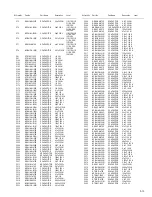
Страница 49: ...143TKA X DIGI TRANSISTOR Q784 RT1P141C X DIGI TRANSISTOR Q784 or UN2111 X TRANSISTOR 11J 11E 11EX 11EY 11EU 11 EE 11U 11UT 12E 12EX Q881 RT1N141C X DIGI TRANSISTOR Q881 or UN2211 X TRANSISTOR 11J 11E 11EX 11EY 11EU 11 EE 11U 11UT 12E 12EX Q902 RT1N141C X DIGI TRANSISTOR Q902 or UN2211 X TRANSISTOR 11J 11E 11EX 11EY 11EU 11 EE 11U 11UT 12E 12EX Q933 2SA1365 F X TRANSISTOR Q934 RT1N141C X DIGI TRANS...

Страница 50: ...r MA8062 M X Z DIODE 11J 11E 11EX 11EY 11EU 11 EE 11U 11UT 12E 12EX D721 MA8062 M X Z DIODE 19UR D722 UDZW6 2B X Z DIODE 11J 11E 11EX 11EY 11EU 11 EE 11U 11UT 12E 12EX D722 or MA8062 M X Z DIODE 11J 11E 11EX 11EY 11EU 11 EE 11U 11UT 12E 12EX D722 MA8062 M X Z DIODE 19UR D723 UDZW6 2B X Z DIODE 11J 11E 11EX 11EY 11EU 11 EE 11U 11UT 12E 12EX D723 or MA8062 M X Z DIODE 11J 11E 11EX 11EY 11EU 11 EE 11...

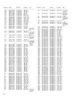
Страница 51: ...50V M C385 QEKJ1HM 475Z E CAPACITOR 4 7uF 50V M C386 QEKJ1HM 475Z E CAPACITOR 4 7uF 50V M C501 NBE41AM 476X TA E CAPACITOR 47uF 10V M C502 QEKJ1CM 107Z E CAPACITOR 100uF 16V M C503 QEKJ1CM 476Z E CAPACITOR 47uF 16V M C504 NCBA1CK 103W C CAPACITOR 0 01uF 16V K C505 NCBA1CK 103W C CAPACITOR 0 01uF 16V K C506 NCB31HK 103X C CAPACITOR 0 01uF 50V K C511 NCBA1CK 103W C CAPACITOR 0 01uF 16V K C512 NCBA1C...

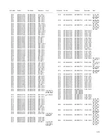
Страница 52: ...12E 12EX Symbol No Part No Part Name Description Local R73 NRSA6AJ 222W MG RESISTOR 2 2kΩ 1 16W J 11E 11EX 11E Y 11EU 11EE 12E 12EX R74 NRSA02J 101X MG RESISTOR 100Ω 1 10W J 11E 11EX 11E Y 11EU 11EE 12E 12EX R81 NRSA6AJ 223W MG RESISTOR 22kΩ 1 16W J 11J 19UR R81 NRSA6AJ 123W MG RESISTOR 12kΩ 1 16W J 11E 11EX 11E Y 11EU 11EE 11U 11UT 12E 12EX R82 NRSA6AJ 512W MG RESISTOR 5 1kΩ 1 16W J R91 NRSA6AJ 2...

Страница 53: ...Ω 1 16W J R728 NRSA6AJ 101W MG RESISTOR 100Ω 1 16W J R732 NRSA6AJ 432W MG RESISTOR 4 3kΩ 1 16W J 11E 11EX 11E Y 11EU 11EE 12E 12EX R734 NRSA6AJ 152W MG RESISTOR 1 5kΩ 1 16W J R735 NRSA6AJ 152W MG RESISTOR 1 5kΩ 1 16W J R736 NRSA6AJ 152W MG RESISTOR 1 5kΩ 1 16W J R737 NRSA6AJ 0R0W MG RESISTOR 0Ω 1 16W J 11J 11E 11EX 11EY 11EU 11 U 11UT 19UR 12E 12EX Symbol No Part No Part Name Description Local R73...

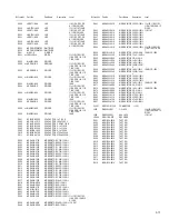
Страница 54: ... CN501 QGB2027MD 22 CONNECTOR B B 1 22 CN701 QGZ1601J1 15 CONNECTOR 1 15 CN702 QNS0283 001 STEERING REMOTE 11E 11EX 11E Y 11EU 12E 1 2EX CN901 QNZ0611 001 16P CONNECTOR J1 QNB0190 001 ANTENNA JACK J321 QNN0802 001 PIN JACK Symbol No Part No Part Name Description Local J801 QNZ0095 001 CONNECTOR 11J 11E 11EX 11EY 11EU 11 U 11UT 19UR 12E 12EX PP1 QZW0010 001 STYLE PIN S703 QSW0648 001Z TACT SWITCH T...

Страница 55: ...RESISTOR 0Ω 1 16W J R630 NRSA63J 271X MG RESISTOR 270Ω 1 16W J R631 NRS181J 621X MG RESISTOR 620Ω 1 8W J R635 NRSA63J 331X MG RESISTOR 330Ω 1 16W J R637 NRSA63J 331X MG RESISTOR 330Ω 1 16W J R639 NRSA63J 561X MG RESISTOR 560Ω 1 16W J 11J 11E 11EX 11EY 11EU 11EE 19UR 12 E 12EX R639 NRSA63J 681X MG RESISTOR 680Ω 1 16W J 11U 11UT R640 NRSA02J 0R0X MG RESISTOR 0Ω 1 10W J Symbol No Part No Part Name De...

Страница 56: ...are not service P2 P3 P4 P5 P5 P7 P1 P3 P6 A9 A8 A19 A15 A16 A17 A18 KIT A10 A11 A12 A13 A14 11E 11EX 11EU11EY 11U 12E 12EX ver Only 11J ver A1 A2 A4 A5 A6 A7 P3 11E 11EX 11EY 12E 12EX ver A1 A2 A3 A4 A7 A20 A21 P3 Only 11EU ver A1 A2 A3 A7 A20 P3 Only 11EE ver A1 A2 A4 A7 P3 Only 11U ver A1 A2 A3 A7 P3 Only 11UT ver A1 A2 A7 P8 Only 19UR ver Only 11J 11U 11UT ver ...

Страница 57: ...OUNTING SLEEVE A 9 GE20235 009A TRIM PLATE 11J A 9 GE20204 015A TRIM PLATE 11E 11EX 11EY 11EU A 9 GE20204 008A TRIM PLATE 11EE 12E 12EX A 9 GE20235 005A TRIM PLATE 11U 11UT A 9 GE20235 002A TRIM PLATE 19UR A 10 VKZ4027 202 PLUG NUT A 11 GE40426 002A MOUNT BOLT A 12 VKZ4328 003 LOCK NUT A 13 QYWWS53A008ZA WASHER 0mm 5 3mm x A 14 GE40130 002A HOOK x2 A 15 BATTERY 3V 11J 11U 11UT A 16 RM RK50C REMOCO...

Страница 58: ...08 9 KD BT11J KD BT11E KD BT11EX KD BT11EY KD BT11EU KD BT11EE KD BT11U KD BT11UT KD BT19UR COPYRIGHT 2008 Victor Company of Japan Limited Lead free solder used in the board material Sn Ag Cu melting point 219 Centigrade Lead free solder used in the board material Sn Cu melting point 230 Centigrade for E EX EY EU EE for EE for J U UT UR for J UR KD BT12E KD BT12EX ...

Страница 59: ...r on some parts of the chassis Therefore pay attention to such burrs in the case of preforming repair of this system Safety precaution Please use enough caution not to see the beam directly or touch it in case of an adjustment or operation check ...

Страница 60: ...CL FSU SSTOP Q OUT AFS CD LO CD RO CD L R CH L R 3 3V SW5V ACC5V VDD5V CD8V 9V ILM 10V ACC REMOTE MEMORY ANT CONT POWER ILLUMINATION ILM ADJ IC801 IC802 JVC BUS IC203 MIC AMP IC202 BT L P F BUSSI BUSSO BUS I O BUSINT BUSSCK SI SO BUSCK CD CHANGER CONTROL MIC J321 CD servo control section Q571 Q976 Q977 PS2 Q711 Q712 CD ON PS2 Q881 DIMMER INPUT DIMMER IN DIM Q902 DIMMER CONTROL X702 32 768kHz SPIND...

Страница 61: ...2k NJM4565V X 0 047 18K IMX9 W IMX9 W UDZW5 6B X UDZW5 6B X 10K 10K 33k 100 100 MA22D23 X 100 47k QAX0401 001 MA22D23 X MA22D23 X MA22D23 X 47k 0 1 1k 100P 100P 100P 100P 100P 12k 27k 100P 100P 100P QNZ0611 001 RT1N141C X RT1P141C X 0 047 ISA1530SC1 R X QFV91HJ 474Z UDZW6 2B X MA22D23 X MA22D23 X MA22D23 X MA22D23 X 100 0 01 2 2 50 100P 0 1 100P 22P 18K 0 0047 0 0047 0 0047 0 0047 820 820 47k 4 7 ...

Страница 62: ...5A 47u 4 7k 100 100 6 8k NJM2878F4 15 X 8 2k 10K 7 5k 0 1 270P 0 027 0 018 220 2 2K 0 1 22 16 47 16 0 01 0 1 0 1 0 0 01 0 150 100p 10 100 100 47K 100 0 0 5 6K 27k 0 0 0 01 0 001 100 100 100 0 1M 0 1 27k 5 6K 150p 0 1 150p 1A3G T1 47 16 22k QTE1E57 475Z QTE1E57 475Z 15K 15K 820p 100k 820p 47 16 5600p 1 5M 3 3K 0 47u RT1N141C X 2SA1365 F X 0 033 0 033 0 1 5 6k 47k 150k 330k 100 16 0 047 0 047 0 01 L...

Страница 63: ...0 0 022 0 022 0 0047 2 7k QGZ1601K1 15S UDZW6 2B X 1000p 0 022 150P 100 100 100 47K 1 2k 820 0 0047 820 820 1 8k 1 2k 820 1 2k 1 8k 820 1u 2 7k 1 8k 2 7k 47K 470 0 0047 0 1 4 7 QLD0518 001 68K 0 0 3 9K 10K 390K 0 0 1SS355W X 180 MA8062 M X MA8062 M X 330 560 620 820 560 MA8051 M X 560 620 330 0 NSPW310CS BTUV MA8062 M X 560 1K 180 270 1K 560 560 0 1 470 NSPW310CS BTUV 330 0 47K 220k 0 0 0 0 0 0 62...

Страница 64: ...571 Q581 Q582 Q711 Q712 Q781 Q782 Q784 Q841 Q881 Q891 Q892 Q902 Q933 Q934 Q976 Q977 R1 R2 R3 R4 R9 R10 R11 R12 R13 R14 R15 R16 R21 R22 R24 R72 R73 R74 R75 R81 R82 R91 R92 R172 R175 R176 R177 R178 R179 R180 R181 R201 R202 R203 R208 R212 R213 R214 C255 R220 R218 R272 R225 R226 R227 R228 R229 R230 R231 R232 R239 R240 R241 R242 R305 R306 R308 R321 R322 R323 R331 R332 R333 R341 R342 R343 R351 R352 R353...

Страница 65: ... C382 C385 C386 C502 C503 C522 C525 C526 C528 C538 C547 C549 C557 C559 C562 C575 C580 C583 C590 C593 C596 C710 C711 C784 C841 C851 C881 C901 C902 C903 C904 C905 C907 C910 C913 C914 C919 CN501 CN701 CN702 CN901 D501 D901 DEBUGCLK FLMDO IC301 IC901 J1 J321 J801 L11 L901 Q502 Q571 C255 R901 RESET S703 TOOL0 TU1 VDD VREF VSS X71 X701 X702 C920 C260 C307 C253 C252 C251 C254 X561 BT CSB BT CLK BT MISO B...

Страница 66: ... M E M O ...
Страница 67: ... No MA387SCH Rev 003 Printed in Japan VPT Mobile Entertainment Division 10 1 1chome Ohwatari machi Maebashi city Gumma ken 371 8543 Japan Victor Company of Japan Limited ...

Отзывы: