2-8
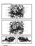
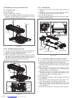
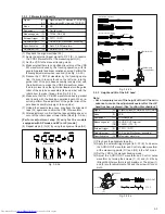
2.2.7 Capstan motor, load gear, control plate
2.2.7.1 Removal
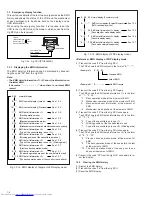
(1) Detach the belt.
(2) Check that the FFC connector on the drum is disconnected.
(3) Release the catch (a) to remove the FFC wire.
(4) Remove the screws (a) to detach the capstan motor.
(5) Remove the screws (b) to detach the fixing plate.
(6) Release the catch (b) to detach the load gear.
(7) Turn the load gear (S/T) in the loading direction to detach it.
(8) Remove the control plate.
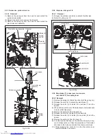
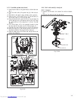
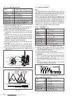
2.2.6.2 Installation (phase adjustment)
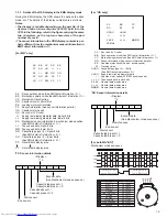
(1) Attach the loading motor assembly to the main deck.
(2) Secure the screw (a).
(3) Solder the wire to section (a).
(4) Arrange the wire along with the position guide (b).
(5) Attach the capstan brake assembly to the main deck.
(6) Place the main deck on the guide hole (a) of the control plate.
(7) Place the main deck on the guide hole (b) of the drive lever.
(8) Place the main deck no guide hole (c) of the control cam to
install the control cam.
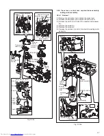
(9) Move the capstan brake in the direction shown by the arrow
(a) to attach the press lever to the shaft (a). Make sure that
the boss of the press lever fits in the control cam, and that
the shaft (b) of the pinch roller arm assembly connects with
the hole of the press lever.
(10) Attach slit washer (a) to shaft (a).
Fig. 2-2-6b
Fig. 2-2-7a
Screw (a)
Shaft (a)
Shaft (b)
PRESS LEVER
Slit washer (a)
Arrow (a)
Guide hole (c)
Loading motor assembly
CONTROL CAM
Guide hole (b)
Shaft (a)
CONTROL
PLATE
DRIVE
LEVER
Capstan brake assembly
Guide hole (a)
Position
guide (b)
Wire (black)
Wire (red)
Section (a)
Catch (a)
Catch (b)
Screws (b)
CONTROL
PLATE
LOAD GEAR
FFC
Load gear (T) assembly
Load gear (S) assembly
LOAD GEAR
FIXING PLATE
Capstan motor assembly
BELT
Screws (a)
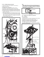
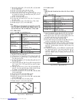
Note:
•
When replacing the worm bearing of the loading motor as-
sembly, attach it according to the following specification.
If worm bearing is not attached correctly, a mechanism
noise may occur. (See Fig. 2-2-6c)
Fig. 2-2-6c
6.8
±
0.2 mm
WORM BEARING
LOADING MOTOR

