background image

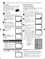
UHF/VHF

OUT(TV)

IN(ANT)

VIDEO

OUT

AUDIO

L

R

UHF/VHF

OUT(TV)

IN(ANT)

VIDEO

OUT

AUDIO

L

R

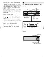
MENU

REC

REW

FF

CH

(AUX)

ENTER

1

2

3

4

5

6

7

0

8

9

SET

TV/VCR

TIMER

A.MONITOR

SP/EP

DISPLAY

CANCEL

C.RESET

TV CH

TV VOL

INPUT

 +

 +

 +

 +

PAUSE

PLAY

STOP

TV POWER

POWER

Remote

TV POWER

TV/VCR

Number keys

CANCEL
C.RESET

REW

REC

STOP

MENU

TV CH–/+

A.MONITOR

AUX

TIMER

CH–/+

SP/EP

PLAY

FF

PAUSE

ENTER

SET–/+

INPUT

POWER

TV VOL–/+

DISPLAY

Connections and VCR channel
Setting

Check contents

Make sure the package contains all of the accessories listed
in “Specifications”.

Situate VCR

Place the VCR on a stable, horizontal surface.

Connect VCR to TV

1

2

3

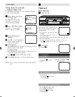
On-screen display

If you press 

DISPLAY

 on the Remote, you can see the current VCR

status on the TV screen. Press 

DISPLAY

 again to exit on-screen

display.
The indications are not recorded even if the VCR is in the recording
mode.

WHILE OPERATING A TAPE

WHILE WATCHING TV

00 : 00 : 00 SP

CH 125

8 : 30 AM THU

STEREO SAP

STEREO

CHANNEL

TAPE

SPEED

REAL TIME COUNTER

STEREO AND

SEPARATE AUDIO

PROGRAM (SAP)

OUTPUT

SELECTION

00 : 00 : 00 SP

8 : 30 AM THU

HI-FI

AUTO TR.
STEREO

OPERATING MODE

TAPE IN

AUTO TRACKING

HI-FI STEREO

AUTO REPEAT

OUTPUT

SELECTION

– Buttons, Connectors and Indicators –

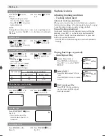
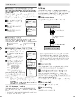
Antenna or cable

Coaxial cable

Flat feeder

Matching transformer

(not supplied)

Back of VCR

To audio/video input connectors

Audio/video cable (not supplied)

To 75 

 terminal

RF cable (supplied)

TV

RF Connection

Disconnect the TV antenna from the TV.
Connect the TV antenna cable to the UHF/VHF IN
terminal on the rear of the VCR.
Connect the supplied RF cable between the UHF/VHF
OUT terminal on the rear of the VCR and the TV’s
antenna input terminal.

AV Connection

(improves picture quality during tape playback.)
If your TV is equipped with audio/video input connectors

Connect the antenna, VCR and TV as shown in the
illustration.
Connect an audio/video cable between the AUDIO/
VIDEO OUT connectors on the rear of the VCR and the
audio/video input connectors on the TV.

• Even if you are using audio/video cables to connect your

VCR to your TV, you must also connect it using the RF
cable. This will ensure that you can record one show while
watching another.

2

3

1

2

1

This Remote transmit A code
signals only; it is not applicable
to B code signals.

DAY AND CLOCK TIME

 4F90201A/Cov-07

11/15/02, 03:56 PM

4

Содержание HR-A592U

Страница 1: ...quipment off and on the user is encouraged to try to correct the interference by one or more of the following measures Reorient or relocate the receiving antenna Increase the separation between the equipment and receiver Connect the equipment into an outlet on a circuit different from that to which the receiver is connected Consult the dealer or an experienced radio TV technician for help Failure ...

Страница 2: ...e National Electrical Code ANSI NFPA 70 provides information with regard to proper grounding of the mast and supporting structure grounding of the lead in wire to an antenna discharge unit size of grounding connectors location of antenna discharge unit connection to grounding electrodes and requirements for the grounding electrode 2 Lightning For added protection for this product during a lightnin...

Страница 3: ...Upon completion of any service or repairs to this product ask the service technician to perform safety checks to determine that the product is in safe operating condition How to use the Remote Before use insert two AAA size batteries into the Remote with the polarity and matched correctly as indicated on the battery compartment or on the lid Point the Remote toward the remote sensor on the target ...

Страница 4: ...N 00 00 00 SP 8 30 AM THU HI FI AUTO TR STEREO OPERATING MODE TAPE IN AUTO TRACKING HI FI STEREO AUTO REPEAT OUTPUT SELECTION Buttons Connectors and Indicators Antenna or cable Coaxial cable Flat feeder Matching transformer not supplied Back of VCR To audio video input connectors Audio video cable not supplied To 75 Ω terminal RF cable supplied TV RF Connection Disconnect the TV antenna from the T...

Страница 5: ... difference of more than 5 minutes exists between the built in clock time and the actual time To Set Auto Clock To Off When shipped from factory AUTO CLOCK option is set to ON But if you do not want Auto Clock set Adjustment To view playback of a recorded tape or to watch a program selected by the VCR s channel selector the TV must be set to channel 3 or 4 video channel when a TV is connected with...

Страница 6: ... SYSTEM SETUP ENTER MENU MENU TIMER REC SET AUTO REPEAT ON OFF ON OFF SAP CH SETUP SYSTEM SETUP TV CATV Selection Access Menu screen then CH Setup screen Press MENU on the Remote Press SET to select CH SETUP then press ENTER Access Menu screen Press MENU on the Remote Press SET to select SYSTEM SETUP then press ENTER ENTER MENU MENU TIMER REC SET AUTO REPEAT ON OFF ON OFF SAP CH SETUP SYSTEM SETUP...

Страница 7: ... 2 NOTE You can t select CH SET UP if you set the channel to L ENTER MENU MENU TIMER REC SET AUTO REPEAT ON OFF ON OFF SAP CH SETUP SYSTEM SETUP Make sure the window side is up the rear label side is facing you and the arrow on the front of the cassette is pointing towards the VCR Basic Playback Load a cassette Playback OR Press STOP EJECT on the VCR 1 2 Do not apply too much pressure when inserti...

Страница 8: ...CH SPEED PRESS ONCE PRESS TWICE SP EP 3X 9X 5X 15X Adjusting tracking condition Tracking Adjustment Automatic tracking adjustment Whenever you insert a tape and start playback automatic tracking starts working and continuously analyzes the signal to enable optimum picture quality during playback Manual tracking adjustment If automatic tracking cannot eliminate noises well during playback press SET...

Страница 9: ...ess STOP or turn off the power The Instant Timer Recording feature provides a simple and convenient way to make a timed recording EXAMPLE Instant Timer Recording for 30 minutes When a TV is connected with an audio video cable turn the TV on and select the video input mode on the TV Load a cassette tape with the erase prevention tab intact The clock display will change in the counter display Press ...

Страница 10: ...recording of up to 8 programs within 1 month ENTER MENU MENU TIMER REC SET AUTO REPEAT ON OFF ON OFF SAP CH SETUP SYSTEM SETUP DATE START END CH ENTER CANCEL MENU DATE START END CH 26 SU ENTER CANCEL MENU DATE START END CH 26 SU 11 00PM 11 30PM 125 EP ENTER CANCEL MENU DATE START END CH 26 SU 11 00PM 11 30PM 125 EP ENTER CANCEL MENU When setting the date in step 3 in the Setting the Timer Recordin...

Страница 11: ...een for about 4 seconds and the program can be viewed or recorded in stereo The Hi Fi STEREO recording procedure is the same as for normal recordings NOTE When using a CATV system stereo TV programs may be transmitted over a mono cable channel In this case the word STEREO will not appear and the sound will be in mono OUTPUT SELECTION The VHS Hi Fi audio system permits high fidelity recording of MT...

Страница 12: ...al connect the audio output connector on the playback VCR to the left audio input connector on this VCR Load cassettes Insert the playback cassette into the playback VCR and the cassette to be recorded on into the recording VCR Select input mode on recording VCR Select the correct external input on the recording VCR On this VCR when using this VCR as the recording VCR Select L when connecting the ...

Страница 13: ... VCR indicator is not lit The erase prevention tab of the video cassette is broken off INPUT is set to the LINE mode SYMPTOM CAUSE POSSIBLE SOLUTION The AC power cord is not connected Connect the AC power cord to the AC outlet Connect it correctly Reconnect the antenna cable Set it to CH 3 or 4 Set the TV channel selector to the 3 or 4 position Press the TV VCR selector button The VCR indicator wi...

Страница 14: ...ifications subject to change without notice Specifications AC 120 V 60 Hz 9 W 1 7 W 5 C to 40 C 41 F to 104 F 20 C to 60 C 4 F to140 F Horizontal only 360 mm x 95 mm x 222 5 mm 14 3 16 x 3 3 4 x 8 3 4 3 2 kg 7 1 lbs VHS NTSC standard 210 min with ST 210 video cassette 630 min with ST 210 video cassette NTSC type color signal and EIA monochrome signal 525 lines 60 fields DA 4 Double Azimuth head he...

Страница 15: ...mounting systems 3 Operational adjustments covered in the Owner s Manual normal maintenance including head cleaning 4 Damage that occurs in shipment due to act of God and cosmetic damage 5 Signal reception problems and failures due to line power surge 6 Products used for commercial purposes including but not limited to rental 7 Accessories 8 Batteries except that Rechargeable Batteries are covered...

Страница 16: ...RTERS JVC SERVICE ENGINEERING COMPANY OF AMERICA DIVISION OF JVC AMERICAS CORP 10 New Maple Avenue Pine Brook NJ 07058 9641 JVC FOR SERVICING Only in U S A WARRANTY REPAIR REPLACEMENT FORM PLEASE COMPLETE THE FOLLOWING PLEASE NOTE P O BOXES ARE NOT ACCEPTABLE NAME __________________________________________________________________ STREET ADDRESS _____________________________________________________...

Отзывы: