


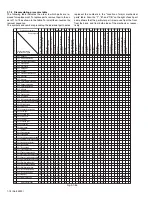


(No.82933)1-21
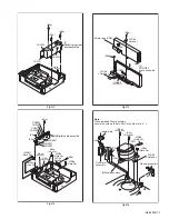
Fig.3-2-3i
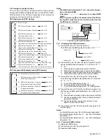
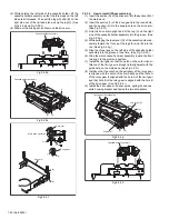
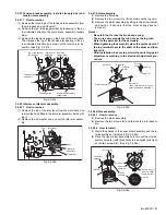
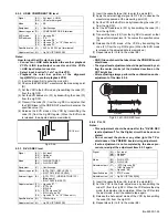
3.2.4 Pinch roller arm assembly
(1) Remove the spring from the hook of the press lever assem-
bly.
(2) Remove the slit washer and remove the pinch roller seat 3.
(See Fig.3-2-4a.)
(3) Remove the pinch roller arm assembly by pulling it up.
Fig.3-2-4a
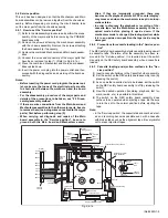
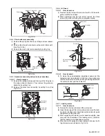
3.2.5 Guide arm assembly and press lever assembly
3.2.5.1
How to remove
(1) Remove the spring and expand the lug of the lid guide in
the arrow-indicated direction. Then remove the guide arm
assembly by pulling it up.
(2) Remove the press lever assembly by pulling it up. (See
Fig.3-2-5a.)
Fig.3-2-5a
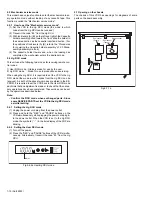
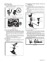
3.2.6 A/C head
3.2.6.1
How to remove
(1) Remove the two screws (A) and remove the A/C head to-
gether with the head base.
(2) When replacing only the A/C head, remove the three
screws (B) while controlling the compression spring.
Fig.3-2-6a
Fig.3-2-6b
3.2.6.2
How to install
(1) To make the post-installation adjustment easier, set the
temporary level as indicated in Fig.3-2-6c. Also make sure
that the screw center (centre) is brought into alignment with
the center (centre) position of the slot.
Fig.3-2-6c
3.2.7 Loading motor
3.2.7.1
How to remove
(1) Remove the belt wound around the worm gear.
(2) Open the two lugs of the motor guide and remove the load-
ing motor, loading motor board assembly and motor guide
altogether by pulling them up.
(3) When replacing the loading motor board assembly, take
care with the orientation of the loading motor. (Install so
that the loading motor label faces upward.)
(4) When the motor pulley has been replaced, choose the fit-
ting dimension as indicated in Fig.3-2-7a.
Relay gear
Drive gear
Limit gear
Guide hole
Notches
Notch
B
A
A
B
Pinch roller seat3
Pinch roller arm assembly
Pinch roller arm
assembly
Spring
Press lever assembly
Tension
spring
Press lever
assembly
Guide arm
assembly
Lug
Lid guide
Head base
Screws(A)
A/C head
Compression
springs
Head base
A/C head board
assembl y
A/C head
Screws(B)
Head base
Head base
Screw
A/C head
A/C head
12.4 mm