background image

1-26 (No.YA385)

3.2

MEMORY IC REPLACEMENT

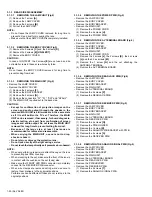
• This model uses the memory IC.
• This memory IC stores data for proper operation of the video and drive circuits.
• When replacing, be sure to use an IC containing this (initial value) data.

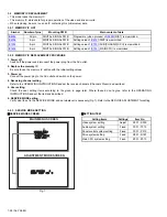
3.2.1 MEMORY IC LIST

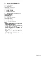
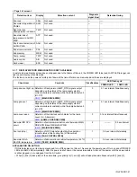
3.2.2 MEMORY IC REPLACEMENT PROCEDURE
1. Power off

Switch off the power and disconnect the power plug from the AC outlet.

2. Replace the memory IC

Be sure to use the memory IC written with the initial setting values.

3. Power on

Connect the power plug to the AC outlet and switch on the power.

4. Receiving channel setting

Refer to the OPERATING INSTRUCTIONS and set the receive channels (Channels Preset) as described.

5. User setting

Check the user setting items according to the given in page later. Where these do not agree, refer to the OPERATING
INSTRUCTIONS and set the items as described.

6. SERVICE MODE setting

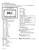
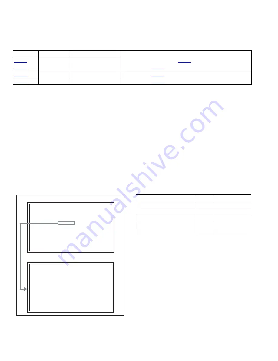
Verify what to set in the SERVICE MODE, and set whatever is necessary (Fig.1). Refer to the SERVICE ADJUSTMENT for setting.

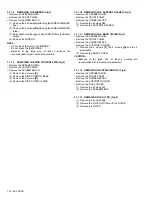
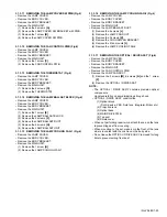
3.2.3 SERVICE MODE SETTING

„

SERVICE MODE SCREEN

Fig.1

„

SETTING ITEM

Simbol

Number of pins


Mounting PWB

Main content of data

IC4003

32-pin

DIGITAL SIGNAL PWB

Programme (video process) of 

IC4001

(DIST) is memorized. 

IC4004

8-pin

DIGITAL SIGNAL PWB

Setting value of 

IC4001

(DIST) is memorized. 

IC7002

8-pin

DIGITAL SIGNAL PWB

Setting value of 

IC7001

(SUB [CHASSIS] CPU) is memorized. 

IC7602

8-pin

DIGITAL SIGNAL PWB

Setting value of 

IC7501 

(MAIN CPU) is memorized. 

MAIN MENU SCREEN

ADJUSTMENT MODE SCREEN

S001 PREPARE    0

S001 PREPARE    0

PAL50  1409  STD  H

PAL50  1409  STD  H

SERVICE MENU

SERVICE MENU

 1.ADJUST

 1.ADJUST

 2.SELF CHECK

 2.SELF CHECK

 3.I2C STOP

 3.I2C STOP

Setting items

Settings

Item No.

Video system setting

Adjust

S001 - S039

Audio system setting

Fixed

T001 - T010

Panel control system setting

Fixed

P001 - P010

Drive system setting

Fixed

D001 - D187

Main CPU system setting

Fixed

Z001 - Z010

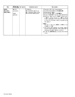
Содержание HD-56ZR7U

Страница 1: ...No YA385 2006 3 D ILA PROJECTION TELEVISION YA385 2006 3 HD 56ZR7J HD 56ZR7U HD 70ZR7J HD 70ZR7U TABLE OF CONTENTS 1 PRECAUTION 1 3 2 SPECIFIC SERVICE INSTRUCTIONS 1 7 3 DISASSEMBLY 1 12 4 ADJUSTMENT 1 29 5 TROUBLESHOOTING 1 39 BASIC CHASSIS RP4 LAMP PROGRAM POWER ...

Страница 2: ...reen Transparent screen unitized fresnel lens lenticular lens aspect ratio 16 9 Screen Size 56 142 cm Measured diagonally H 124 cm V 69 7 cm 70 178 cm Measured diagonally H 155 5 cm V 87 2 cm Audio Power Output 10 W 10 W Speaker 10 cm round type 2 Aerial terminal VHF UHF 75 Ω unbalanced coaxial EXT 1 EXT 2 EXT 3 Input Output 21 pin Euro connector SCART socket 3 EXT 4 Input Component Video 1125i 75...

Страница 3: ...ts that indicate evidence of overheating should be replaced Always use the manufacturer s replacement components 6 Isolation Check Safety for Electrical Shock Hazard After re assembling the product always perform an isolation check on the exposed metal parts of the cabinet antenna terminals video audio input and output terminals Control knobs metal cabinet screw heads earphone jack control shafts ...

Страница 4: ...nt of heat during operation Ensure that sufficient space is available around the TV to allow satisfactory cooling 1 3 LAMP UNIT HANDLING CAUTION 1 3 1 PRECAUTION FOR LAMP UNIT The lamp emits high intensity white ultraviolet and infrared light Do not look directly at the light during service Also do not touch the lamp directly as it presents a burn hazard Handle with extra care This lamp emits high...

Страница 5: ...er to the USERS GUIDE for a detailed operating description 1 Press the MENU key to select SET UP 2 Select the LAMP TIMER RESET with keys 3 Enter the LAMP TIMER RESET mode and the message will appears 4 Press the OK key while the above message appears on the screen 5 Turn off the power then turn on the power 6 The lamp timer has now been reset as before the HOW TO CONFIRM LAMP OPERATING TIME 1 3 6 ...

Страница 6: ...justment and drive convergence projection adjustment are required 1 5 SCREEN HANDLING CAUTIONS 1 5 1 SCREEN STORAGE Store the SCREEN ASS Y in a standing position in order to avoid deformation If the screen is stored horizontally there is risk of deforming the screen face When necessary to place the SCREEN ASS Y horizontally position the screen side upwards and sure to place spacers between the scr...

Страница 7: ...n digital technology to give you a natural looking picture MOVIE THEATRE This function displays a cinema film picture more smoothly and naturally on the screen 3D SOUND You can enjoy sounds with a widerambience 2 3 MAIN DIFFERENCE LIST Be sure to carry out the following operation at the end of the procedure SERVICE MENU SERVICE MENU 1 ADJUST 1 ADJUST 2 SELF CHECK 2 SELF CHECK 3 I2C STOP 3 I2C STOP...

Страница 8: ...B W 75Ω Used Used Not used 8 FUNCTION SW SLOW SW Low 0V 3V High 8V 12V High impedance Used Used Used 9 GND G Used Used Used 10 SCL T V LINK Not used Used SCL2 TV LINK Not used 11 G input 700mV B W 75Ω Used Used Not used 12 SDA Not used Used SDA2 Not used 13 GND R Used Used Used 14 GND YS Used Not used Not used 15 R C input R 700mV B W 75Ω C 300mV P P 75Ω Used R Used C2 R Not used 16 Ys input FAST ...

Страница 9: ...trast ratio 1000 1 Aperture ratio 93 or more Effective pixel measurement 0 7 inch R DEVICE G DEVICE B DEVICE Lamp unit Incident light Device B RG B B R G R Projection light G Mirror Mirror Mirror FRONT DEVICE UNIT SECTION TOP VIEW Device Device Incident light Pixel FRONT Incident light Projection light Glass substrate Transparent electrode Reflective pixel electrode Back Plane Liquid crystal Flat ...

Страница 10: ... O Green for OSD 30 A12 O Program ROM address for main CPU 94 P5 15 O Green for OSD 31 VSS33 GND 95 TRIG_IN O Green for OSD 32 VDD33 I 3 3V 96 TRIG_OUT O Green for OSD 33 A4 O Program ROM address for main CPU 97 P6 2 O Green for OSD 34 A3 O Program ROM address for main CPU 98 P6 3 O I2 C bus clock for main memory 35 A2 O Program ROM address for main CPU 99 P6 4 I O I2 C bus Data for main memory 36...

Страница 11: ...nect CN01P for Frash ROM type 24 OSC0 O System clock osillation crystal 16MHz 74 SBT5 RT5 I Clock for writing on board connect CN01P for Frash ROM type 25 MODE I Single chip mode H Fixed 75 NMI I 3 3V power supply 26 BS1 5CTL O Not used Digital tuner power reset control 76 COMP I Not used AV COMPULINK lll control 27 A92RES O Reset for IC1001 3D YC SEP COLOUR DEMODULAT Reset H 77 REMO I Remote cont...

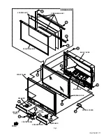
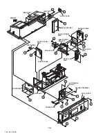
Страница 12: ... Remove the CENTRE COVER 3 1 1 4 REMOVING THE SPEAKER Fig 1 Remove the SPEAKER GRILL 1 Remove the 8 screws D 2 Remove the SPEAKER 3 1 1 5 REMOVING THE FRONT PANEL Fig 1 Remove the SPEAKER GRILL Remove the SPEAKER 1 Remove the 12 screws E and the 10 screws F 2 Remove the FRONT PANEL CAUTION Because of the large size at least 2 persons are recommended for removal and reassemble 3 1 1 6 REMOVING THE ...

Страница 13: ...No YA385 1 13 Fig 1 FRONT SCREEN BLOCK SCREEN BRACKET SCREEN ASS Y FRONT BRACKET SPEAKER BACK COVER SPEAKER CENTRE COVER FRONT PANEL SPEAKER GRILL FRONT LED PWB SCREEN BLOCK MAIN BODY B F D D C E G H H A ...

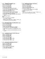
Страница 14: ...e the 2 screws D 4 Remove the SIDE CONTROL PWB 3 1 1 10 REMOVING THE SUPPORT HOLDER Fig 2 Remove the SPEAKER GRILL Remove the FRONT PANEL Remove the SCREEN BLOCK 1 Remove the 2 screws E 2 Remove the SUPPORT HOLDER 3 1 1 11 REMOVING THE BACK COVER Fig 2 Remove the SPEAKER GRILL Remove the FRONT PANEL Remove the SCREEN BLOCK Remove the SUPPORT HOLDER 1 Remove the 6 screws F the 2 screws G and the 2 ...

Страница 15: ...T MAIN BODY SUPPORT HOLDER SIDE CONTROL PWB SIDE CONTROL BASE SPEAKER BOX SPEAKER BOX MIRROR MIRROR HOLDER top MIRROR HOLDER side MIRROR HOLDER side BACK COVER FILTER COVER FILTER FILTER COVER FILTER G G D C E J J B A B F H K K ...

Страница 16: ...crews H 2 Remove the FRONT PANEL CAUTION Because of the large size at least 2 persons are recommended for removal and reassemble 3 1 2 7 REMOVING THE SCREEN BLOCK Fig 3 Remove the SPEAKER GRILL Remove the CENTRE PANEL Remove the FRONT PANEL 1 Remove the 6 screws J and the 8 screws K 2 Remove the SCREEN BLOCK CAUTION Place the SCREEN BLOCK on a flat table without fail Because of the large size at l...

Страница 17: ... FRONT SPEAKER SPEAKER FRONT LED PWB CENTRE PANEL SPEAKER GRILL CENTRE COVER SPEAKER GRILL BACK COVER FRONT PANEL SCREEN BRACKET FRONT BRACKET SCREEN BLOCK SCREEN ASS Y SCREEN BLOCK MAIN BODY H A B E J L L L L K D F G C F ...

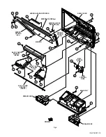
Страница 18: ...1 Remove the 6 screws G and the 1 screw H 2 Remove the BACK COVER BRACKET REAR 3 Remove the 8 screws J the 4 screws K and the 1 screw L 4 Remove the BACK COVER BRACKET both L R and FRONT 3 1 2 11 REMOVING THE SIDE CONTROL PWB Fig 4 Remove the SPEAKER GRILL Remove the CENTRE PANEL Remove the FRONT PANEL Remove the SCREEN BLOCK 1 Remove the 4 screws M 2 Remove the SIDE CONTROL BASE 3 Remove the 2 sc...

Страница 19: ...RROR HOLDER top MIRROR HOLDER side MIRROR HOLDER BRACKET top MIRROR HOLDER side SIDE CONTROL PWB SIDE CONTROL BASE SPEAKER BOX SPEAKER BOX MAIN BODY BACK COVER BRACKET L R BACK COVER BRACKET REAR BACK COVER BRACKET FRONT F D E C B A E D M N P P P P Q R F K L K G J J H G ...

Страница 20: ...TE When not performing repair work attach the cap on the lens to preventing dust from covering When mounting to the set make sure the front of the lens is in contact with the cushion on the set body side Make sure that FRONT LED PWB connector is completely connect to the RECEIVER PWB connector When wire clamps are removed during work use care to restore them precisely to their original positions P...

Страница 21: ... TERMINAL BOARD Remove the PWB HOLDER 1 Remove the 1 screw V 2 Remove the EARTH WIRE 3 Remove the 1 screw W 4 Remove the DIGITAL SIGNAL PWB CAUTION Make sure to perform the SYSTEM SETTEING when DIGITAL SIGNAL PWB is replaced Especially because the value of S039 ILA COM might been changed go through next steps to confirm the set ting value with the remote control unit 1 Press INFORMATION key and MU...

Страница 22: ...LOG SIGNAL PWB REAR JACK PWB ANALOG PWB BRACKET PWB HOLDER EARTH WIRE REGULATOR PWB DIGITAL SIGNAL PWB SHIELD COVER MAIN UNIT POWER PWB AV TERMINAL BOARD POWER CORD BODY COVER ANTENNA TERMINAL LAMP COVER LAMP UNIT FRONT F C D R S T Q P U W H G J M N K V B A E L ...

Страница 23: ...the MAIN UNIT 1 Remove the 1 screw H 2 Remove the LAMP COOLING FAN 1 3 1 3 16 REMOVING THE LAMP COOLING FAN 2 Fig 6 Remove the LAMP COVER Remove the BODY COVER Remove the BODY BRACKET Remove the MAIN UNIT Remove the LAMP BALLAST DUCT 1 Remove the 4 screws J 2 Remove the LAMP FAN DUCT 3 Remove the 2 screws K 4 Remove the COOLING FAN BRACKET 5 Remove the 4 fan mounts L 6 Remove the LAMP COOLING FAN ...

Страница 24: ...OVER Remove the BODY BRACKET Remove the MAIN UNIT 1 Remove the 5 screws V 2 Remove the PROJECTION LENS 3 1 3 20 REMOVING THE OPTICAL BLOCK COOLING FAN Fig 6 Remove the LAMP COVER Remove the BODY COVER Remove the BODY BRACKET Remove the MAIN UNIT Remove the FAN CONTROL PWB Remove the LAMP FAN DUCT Remove the OPTICAL DRIVE ASS Y 1 Remove the 2 screws W 2 Remove the SIROCCO TOP CASE 3 Remove the 2 sc...

Страница 25: ... CASE TEMP SENSOR PWB UNIT BASE LAMP COVER SW PWB LAMP COVER SW BRACKET FAN CONTROL PWB THERMOSTAT LAMP BALLAST UNIT LAMP BALLAST DUCT LAMP BALLAST BRACKET LAMP FAN DUCT COOLING FAN BRACKET COOLING FAN HOLDER SHIELD TOP CASE TOP DUCT OPTICAL BLOCK COOLING FAN LAMP COOLING FAN 2 LAMP COOLING FAN 1 OPTICAL BLOCK G D J K H A B X W L F E T C N U M Y R Q P V ...

Страница 26: ...escribed 6 SERVICE MODE setting Verify what to set in the SERVICE MODE and set whatever is necessary Fig 1 Refer to the SERVICE ADJUSTMENT for setting 3 2 3 SERVICE MODE SETTING SERVICE MODE SCREEN Fig 1 SETTING ITEM Simbol Number of pins Mounting PWB Main content of data IC4003 32 pin DIGITAL SIGNAL PWB Programme video process of IC4001 DIST is memorized IC4004 8 pin DIGITAL SIGNAL PWB Setting va...

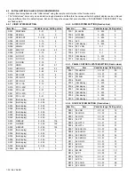
Страница 27: ...igiPure AUTO MOVIE THEATRE AUTO COLOUR MANAGEMENT ON PICTURE MANAGEMENT ON COLOUR SYSTEM TV Depends on PR CH EXT AUTO 4 3 AUTO ASPECT PANORAMIC Setting item Setting position STEREO I II Stereo sound BASS Centre TREBLE Centre BALANCE Centre 3D SOUND OFF BBE ON Setting item Setting position SLEEP TIMER OFF CHILD LOCK ID NO 0000 All CH off APPEARANCE TYPE D BLUE BACK ON FAVOURITE SETTING Reset ILLUMI...

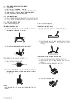
Страница 28: ...he tweezers and remove the chip part Transistors diodes variable resistors etc 1 Apply extra solder to each lead 2 As shown in the figure push the part with tweezers and alternately melt the solder at each lead Shift and remove the chip part NOTE After removing the part remove remaining solder from the pattern 2 How to install Chip parts Resistors capacitors etc 1 Apply solder to the pattern as in...

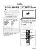
Страница 29: ...Remote control unit 4 4 BASIC OPERATION OF SERVICE MODE 4 4 1 HOW TO ENTER THE SERVICE MODE 1 Press the INFORMATION key and MUTING key simultaneously to enter the SERVICE MODE Fig 1 Fig 1 NOTE Before entering the SERVICE MODE confirm that the setting of VCR TV DVD switch of the REMOTE CONTROL UNIT is at the TV side If the switch has not been properly set you cannot enter the SERVICE MODE When a nu...

Страница 30: ...ETTING VALUE DATA VOL VOL key For change of the setting values up down MEMORY OF SETTING VALUE DATA Changed setting value is memorized by pressing MUTING key PAL50 PAL50Hz Composite S video PAL60 PAL60Hz Composite S video SECAM SECAM NTSC3 NTSC3 58 NTSC4 NTSC4 43 525I 525i Component 525P 525p 625I 625i Component 625P 625p 1125I5 1125i 50Hz 1125I6 1125i 60Hz RGB5 RGB 525i RGB6 RGB 625i PCVGA PC VGA...

Страница 31: ...synthesis of RGB 2 ADJUSTMENT COLOUR MODE Presently selected ADJUSTMENT COLOUR MODE is displayed SELECTION OF SETTING ITEM CH CH key For moving the selected RGB BOX PATTERN up down pix el by pixel VOL VOL key For moving the selected RGB BOX PATTERN left right pixel by pixel Blue key For resetting the data INFORMATION key For selecting the ADJUSTMENT COLOUR MODE BACK key For returning to the SERVIC...

Страница 32: ...isplay 0 255 0 S026 Not display 0 255 0 S027 Not display 0 255 0 S028 Not display 0 255 0 S029 Not display 0 255 0 S030 R DRIVE 0 255 116 S031 G DRIVE 0 255 128 S032 B DRIVE 0 255 105 S033 Not display 0 255 0 S034 Not display 0 255 0 S035 Not display 0 255 0 S036 Not display 0 255 0 S037 Not display 0 255 0 S038 Not display 0 255 0 S039 ILA COM 0 1 0 Item No Item Variable range Setting value T001 ...

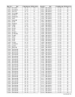
Страница 33: ... 00 FF 00 Item No Item Variable range Setting value D070 Not display 00 FF 00 D071 Not display 00 FF 00 D072 Not display 00 FF 00 D073 Not display 00 FF 00 D074 Not display 00 FF 00 D075 Not display 00 FF 00 D076 Not display 00 FF 00 D077 Not display 00 FF 00 D078 Not display 00 FF 00 D079 Not display 00 FF 00 D080 Not display 00 FF 00 D081 Not display 00 FF 00 D082 Not display 00 FF 00 D083 Not d...

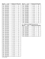
Страница 34: ...splay 00 FF 00 D157 Not display 00 FF 00 D158 Not display 00 FF 00 D159 Not display 00 FF 00 D160 Not display 00 FF 00 D161 Not display 00 FF 00 D162 Not display 00 FF 00 D163 Not display 00 FF 00 D164 Not display 00 FF 00 D165 Not display 00 FF 00 D166 Not display 00 FF 00 D167 Not display 00 FF 00 D168 Not display 00 FF 00 D169 Not display 00 FF 00 Item No Item Variable range Setting value D170 ...

Страница 35: ...ction lens Item Measuring instrument Test point Adjustment part Description DRIVE CONVERGENCE Remote control unit 9 RGB BOX PATTERN 1 Press the INFORMATION key and MUTING key simultaneously to enter the SERVICE MODE 2 Press the 9 key to select RGB BOX PATTERN MODE from the SERVICE MODE 3 Set the adjustment colour mode to R to set the red colour adjustment mode 4 Adjust to minimize the vertical col...

Страница 36: ...EMP to NORMAL 5 Select 1 ADJUST from the SERVICE MODE 6 Set S030 R DRIVE S031 G DRIVE and S032 B DRIVE to 128 7 Set S001 adjustment setting mode change to 8 and it changes to the 625i A D offset ad justment setting mode 8 Adjust S008 625i Cb offset and S009 625i Cr offset to lose the gap red line green line and blue line which appears at both ends of a white part at the centre of the screen 9 Set ...

Страница 37: ...b screen Cr offset S030 R DRIVE Red drive S031 G DRIVE Green drive S032 B DRIVE Blue drive 1 Set PICTURE MODE to STANDARD 2 Set ZOOM to FULL 3 Set COLOUR TEMP to NORMAL 4 Set MULTI SCREEN to 2 pictures 5 Receive a PAL 30 all white pattern signal on the Right screen At the same time set the Left screen in VIDEO 1 mode No signal 6 Select 1 ADJUST from the SERVICE MODE 7 Set S030 R DRIVE S031 G DRIVE...

Страница 38: ...rom the SERVICE MODE 6 Adjust to keep one of S030 Red drive S031 Green drive or S032 Blue drive unchanged then lower the other two so that the all white screen is equally white throughout NOTE Set one or more of S030 S031 and S032 to 128 7 Check that white balance is properly tracked from low light to high light If the white balance tracking is deviated adjust to correct it 8 Press the MUTING key ...

Страница 39: ...4 FAILURE HISTORY Failure history can be counted up to 9 times for each item When the number exceeds 9 display will remain as 9 Failure history will be stored in the memory unless it has been deleted NOTE Only SYNC with without sync signals will be neither counted nor stored 5 1 5 POINTS TO NOTE WHEN USING THE SELF CHECK FEATURE In addition to circuit failures abnormal operation the following case...

Страница 40: ...WAKE If it checks whenever sync communication with SHM performed and no reply of ACK signal an error will be counted Digital tuner DIGI Not used Main memory MEM Confirmation of reply of ACK signal which uses I2C communication IC7602 DIGITAL SIGNAL PWB SDA If it checks whenever I2C communication is performed and no reply of ACK signal an error will be counted AV select switch AVSW Same as above IC3...

Страница 41: ...SH Not used Panel communication PNL Not used Sub memory MEM Not used Temp sensor TMP Not used Audio control AIO Not used Card viewer ESS Not used Check item Contents Classifications LED flash cycle POWER LED LAMP LED Lamp does not light up Detection of lamp return LAMP_RTN signals output depending on the status of the lamp supply electric current monitored constantly within the lamp ballast unit H...

Страница 42: ... No YA385 ILA Display Category 12 3 chome Moriya cho Kanagawa ku Yokohama city Kanagawa prefecture 221 8528 Japan Victor Company of Japan Limited VPT Printed in Japan ...

Отзывы: