1-12 (No.YF031)
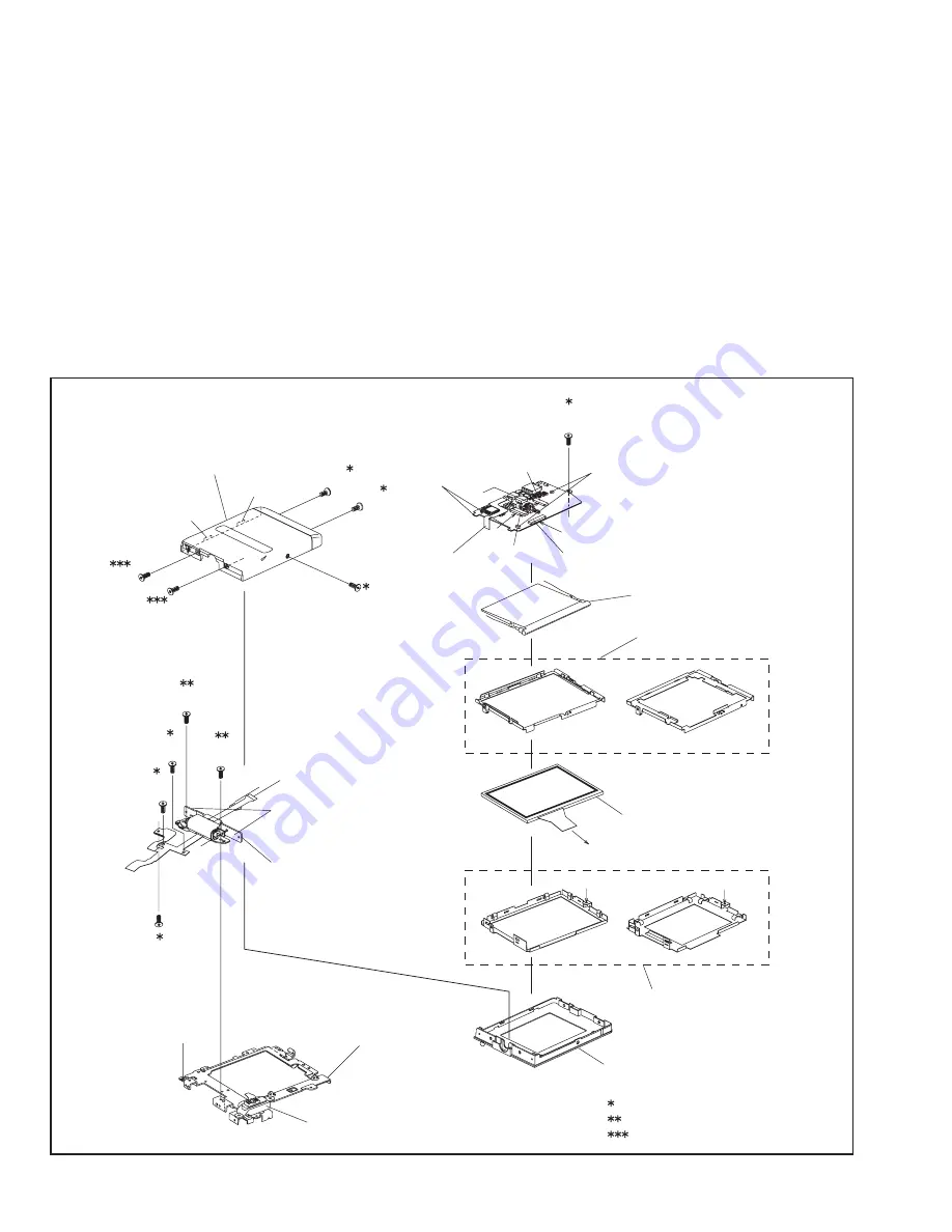
3.2.3 DISASSEMBLY of [9] MONITOR ASSEMBLY
z
CAUTIONS
(1) During the procedure, be careful in handling the LCD
MODULE,etc., especially not to damage or soil the mon-
itor screen. If it is soiled with fingerprints, etc., gently
clean it with chamois or the cleaning cloth.
(2) Since the BACKLIGHT is soldered to the BOARD AS-
SEMBLY (SD9), the BACKLIGHT should not be separat-
ed from the BOARD ASSEMBLY except when replacing
the BACKLIGHT.
(3) Remove the POWER (OPE) UNIT if necessary.
z
Disassembly
(1) Remove the three screws (1-3) so that the FPC moves
easily.
(2) Remove the two screws (4 and 5), and remove the MON-
ITOR ASSEMBLY from the FRAME (UP) ASSEMBLY.
(3) While removing the five screws (6-10) in numerical order
and disengaging the two hooks (L9a and L9b) in alpha-
betical order, remove the MONITOR COVER ASSY.
(4) Remove the SWITCH BOARD from the MONITOR
CASE.
(5) Unlock the two connectors CN9a and CN9b, and raise
and remove the HINGE UNIT ASSEMBLY.
NOTE9a:
During the procedure, be careful in handling the FPC
ASSEMBLY.
(6) Unlock one connector CN9c, and remove the FPC.
(7) Remove one screw (11), and remove the MONITOR
BOARD ASSEMBLY together with the BACKLIGHT.
(8) Remove the LCD BRACKET (2).
(9) Remove the LCD MODULE.
(10) Remove the LCD BRACKET (1).
Fig.3-2-3
F1
F2
F3
a
MONITOR BOARD
ASSEMBLY[0][5]
a
F1
e
F2
F3
e
For 3.0INCH
For 2.5INCH
For 2.5INCH
For 3.0INCH
a
MONITOR COVER ASSEMBLY
2
3
4
5
(S9a)
(S9a)
(S9a)
(S9a)
7
8
6
9
10
(S9d)
(S9d)
(S9c)
(S9e)
(S9e)
HINGE UNIT ASSEMBLY
NOTE9a
L9a
L9b
L9c
11
(S9f)
SWITCH BOARD
ASSEMBLY
L9d
SD9
CN9a
CN9c
CN9b
BACK LIGHT
LCD BKT (2)
LCD MODULE
LCD BKT (1)
MONITOR CASE
1
(S9a)
FRAME(UP)ASSEMBLY
POWER(OPE)UNIT
d
d
: 0.098N
.
m(1.0kgf
.
cm)
: 0.196N
.
m(2.0kgf
.
cm)
: 0.246N
.
m(2.5kgf
.
cm)
Содержание GR-DX77US
Страница 2: ...1 2 No YF031 SPECIFICATION ...


