EN
49
T
W
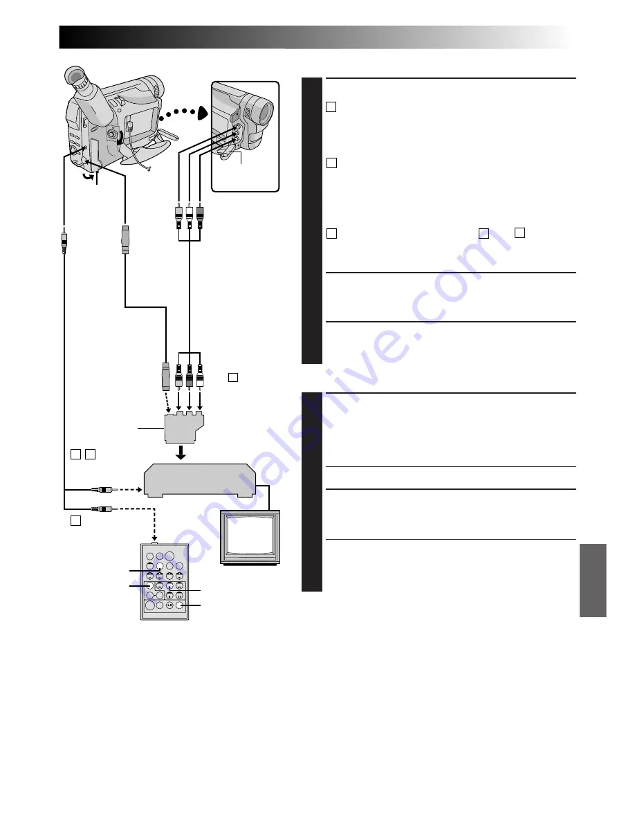
MAKE CONNECTIONS
1
CONNECT TO . . .
A
JVC VCR EQUIPPED WITH REMOTE PAUSE
TERMINAL
Connect the editing cable to the Remote PAUSE
terminal.
B
JVC VCR NOT EQUIPPED WITH REMOTE
PAUSE TERMINAL BUT EQUIPPED WITH
R.A. EDIT CONNECTOR
Connect the editing cable to the R.A.EDIT
connector.
C
VCR OTHER THAN TYPE
A
OR
B
Connect the editing cable to the RM-V712U’s
PAUSE-IN connector.
2
PREPARE CAMCORDER
Insert a recorded tape and set the Power Switch to
“PLAY”.
3
PREPARE VCR
Turn the power on, insert a recordable tape and
engage the AUX mode (refer to VCR’s instructions).
SELECT SCENES
4
START SOURCE PLAYBACK
First set the Power Switch to “PLAY”. Press
PLAY
(
4
)
and then press
R.A. EDIT ON/OFF
on the remote
control. Make sure to point the remote control at the
camcorder’s remote sensor.
•The Random Assemble Editing Menu appears.
5
EXECUTE FADE/WIPE IN
(IF NECESSARY)
Press
FADE/WIPE
on the remote control.
•Cycle through the effects by pressing repeatedly,
and stop when the one you want is displayed.
•You cannot use a Picture Wipe/Dissolve at the
beginning of Programme 1.
CONTINUED ON NEXT PAGE
FADE/WIPE
PLAY
R.A.EDIT
ON/OFF
DISPLAY
Open the
cover.
White to Audio
Output L
Red to Audio
Output R
A
B
To Remote
PAUSE
S-Video cable
(provided)
To
S-VIDEO
OUT
To J
terminal
(JLIP)
RM-V712U
(provided)
VCR
TV
C
To PAUSE-IN
NOTES:
●
Before Random Assemble Editing, make sure the indications do not appear on the TV monitor. If they appear
during Random Assemble Editing, they will be recorded onto the new tape. To clear the Playback Sound
Mode Display, press
DISPLAY
on the remote control. Select “DISPLAY” and “TIME CODE” from the
Playback Menu (
Z
pg. 38) to show or hide the Date/Time and the Time Code on the recording. To show or
hide all indications except for the Random Assemble Editing Menu, press
DISPLAY
on the camcorder for
longer than 1 second. When Random Assemble Editing starts, its indications disappear and are not recorded
on the new tape.
●
Set the video out select switch of the cable adapter as required:
Y/C: When connecting to a TV or VCR which accepts Y/C signals and uses an S-Video cable.
CVBS: When connecting to a TV or VCR which does not accept Y/C signals and uses an audio/video cable.
Yellow
to Video
Output
Open the
cover.
Editing cable
(provided)
A/V cable
(provided)
“Y/C”/“CVBS”
video out
select switch
If your VCR
has the SCART
connector, use
the provided
cable adapter.
To AUDIO,
VIDEO
and
S
-IN
connectors
Содержание GR-DVF1
Страница 62: ...62EN INDEX Controls Connectors And Indicators R T E 1 u i y r q 2 o p Q 3 4 5 6 8 7 9 0 t e w W ...
Страница 70: ...MEMO ...
Страница 71: ...MEMO ...


