1-12 (No.YF091)
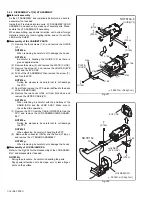
3.2.3 DISASSEMBLY of [8] UPPER ASSEMBLY
z
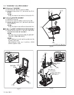
[16] Removing VF ASSEMBLY
(1) Remove the FPC from the connector (CN8a).
(2) Remove the three screws (1-3), and remove the VF AS-
SEMBLY.
NOTE8a:
During the procedure, be careful not to break the FPC.
z
[17] Removing MONITOR ASSEMBLY
(1) Remove the screw (4).
(2) Remove the connector (CN8b), and remove the FPC.
(3) Remove the two screws (5, 6), and remove the MONI-
TOR ASSEMBLY.
NOTE8b:
During the procedure, be careful not to break the FPC.
z
[18] Removing MONITOR OPERATION BOARD ASSEMBLY
(1) Remove the five screws (7-11), and remove the MONI-
TOR OPERATION BOARD ASSEMBLY.
NOTE8c:
When removing, be careful in handling the parts (BUT-
TON (SET), KNOB(VIDEO/DSC)).
NOTE8d:
When attaching, be careful with the positions and the
directions of the parts.
After attachment, make sure to perform a SLIDE
SWITCH operation check.
Fig.U1
Fig.U2
Fig.U3
[16]
1
(S8a)
2
(S8a)
3
(S8b)
A
A
L8b
L8a
a
CN8a
NOTE8a
CN8a
FPC
<NOTE8a>
a
a
[17]
5
(S8c)
6
(S8c)
4
(S8a)
: 0.147N
㨯
m (1.5kgf
㨯
cm)
FPC
L8c
L8d
<NOTE8b>
NOTE8b
NOTE8c,d
NOTE8c,d
[18]
BUTTON(SET)
KNOB(VIDEO/DSC)
FPC
7
(S8a)
8
(S8a)
11
(S8b)
10
(S8a)
9
(S8a)
CN8b
L8d
L8c


