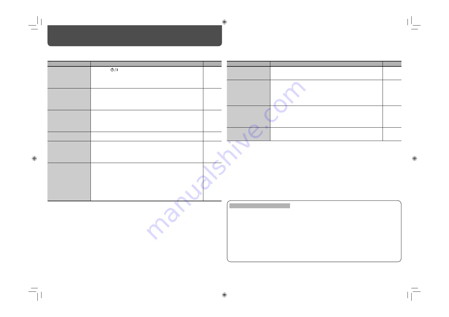
JVC DT-V9L3DY - Broadcast Studio Monitor Скачать руководство пользователя страница 18

18

Troubleshooting

Solutions to common problems related to the monitor are described here. If none of the solutions presented here 
solve the problem, unplug the monitor and consult an authorized dealer or service center.

Symptom

Probable cause and corrective action

Page

No power supply

• Press the 

 button.

•  Turn on the POWER switch or DC switch on the rear panel.
•  Firmly insert the AC power plug or DC 12 V power plug.
•  When using a DC 12 V power supply, charge the battery or replace it 

with a charged one.

6
8
8
8

No picture with the 
power on

•  Select the correct input.
•  Connect the signal cable firmly.
•  Turn on the power of the connected component and set the output 

correctly.

•  Check whether the input signal format is acceptable on the monitor.

6
8

9

No sound 

•  Adjust the volume level.
•  Deactivate the muting function.
•  Connect the signal cable firmly. 
•  Turn on the power of the connected component and set the output 

correctly.

6
6
8

“OTHERS” or “Out of 
range” appears.

•  Check whether the input signal format is acceptable on the monitor.

7, 9

“NO SYNC” appears.

•  Select the correct input.
•  Connect the signal cable firmly. 
•  Turn on the power of the connected component and output video 

signals. Or, check whether the video output of the component (video 
output setting of the VCR) is set correctly.

6
8

Wrong color, no color

•  Adjust each picture adjustment knob on the front panel or adjust the 

items of “PICTURE SUB ADJ.” in the SET-UP MENU. Or, perform 
“reset” in “PICTURE SUB ADJ.” 

•  Check if the screen mode is other than normal screen, by using SCR. 

CHK. button.

•  Select the proper color system (“COLOR SYSTEM”) in “FUNCTION 

SETTING” of the SET-UP MENU.

•  Adjust the items of “WHITE BALANCE SET.” in the SET-UP MENU. 

Or, perform “reset” in “WHITE BALANCE SET.”

6, 14

6

14

14

The following are not malfunctions.

•  When a still image is displayed for a long time, it may remain indistinctly on the screen after the picture has 

changed. Though the remaining picture will disappear after a while, there may be a case that it remains 
for a long period depending on the length of time the still image was displayed for. This is due to the 
characteristics of the LCD display and is not a malfunction.

•  Red spots, blue spots and green spots on the panel surface are a normal characteristic of LCD displays, 

and not a problem. The LCD display is built with very high precision technology; however, be aware that a 
few pixels may be missing or constantly lit.

•  The following symptoms are problems only when pictures or sounds are not played back normally.

– A slight electric shock occurs when you touch the monitor.
– The top and/or rear panel of the monitor becomes hot.
– The monitor emits a cracking noise.
– The monitor emits a mechanical noise.

Symptom

Probable cause and corrective action

Page

The picture becomes 
blurred.

•  Adjust the picture contrast or brightness by using the adjustment 

knobs on the front panel. Or, adjust “CONTRAST” or “BRIGHT” of 
“PICTURE SUB ADJ.” in the SET-UP MENU. 

6, 14

Wrong picture position, 
wrong picture size.

•  Check whether the input signal format is acceptable on the monitor.
•  Check the setting of “ASPECT” in the MAIN MENU.
•  Adjust the horizontal picture position in “H. POSITION” of the SET-

UP MENU.

•  For some signals, the picture cannot be displayed fully in the 

effective screen area. There is no sure method to solve this problem.

7, 9

10
14

Some items do not 
appear on the menu.

•  The items which are not available for the current input or the current 

input signal are not displayed on the menu. Change the input or the 
input signal.

•  The items controlled by the MAKE system do not appear on the 

menu.

16

Buttons on the monitor 
do not work.

•  Set “CONTROL LOCK” in the SET-UP MENU to “OFF.”
•  You cannot use the buttons for the items controlled by the MAKE 

system. Disable the external control.

15
16

DT-V9L3D_J_en.indb   18

DT-V9L3D_J_en.indb   18

09.8.7   1:30:37 PM

09.8.7   1:30:37 PM

Содержание DT-V9L3DY - Broadcast Studio Monitor

Страница 1: ...ce the risk of electric shock Do not remove cover or back No user serviceable parts inside Refer servicing to qualified service personnel RISK OF ELECTRICAL SHOCK DO NOT OPEN The lightning flash with arrowhead symbol within an equilateral triangle is intended to alert the user to the presence of uninsulated dangerous voltage within the product s enclosure that may be of sufficient magnitude to con...

Страница 2: ...ly the accessory cord designed for this product to prevent shock Slots and openings in the cabinet are provided for ventilation These ensure reliable operation of the product and protect it from overheating These openings must not be blocked or covered Never push objects of any kind into this product through openings as they may touch dangerous voltage points or short circuit the parts which could...

Страница 3: ... the manufacturer s instructions 8 Do not install near any heat sources such as radiators heat registers stoves or other apparatus including amplifiers that produce heat 9 Do not defeat the safety purpose of the polarized or grounding type plug A polarized plug has two blades with one wider than the other A grounding type plug has two blades and a third grounding prong The wide blade or the third ...

Страница 4: ...stand height You can select the stand height according to your preference higher position or lower position To change the stand height change the position of the screw hole used for attaching the stand When shipped from factory the stand is attached to the higher position Before adjusting the stand height set the monitor angle to 0 CAUTION Lay the monitor on a cloth with the LCD panel facing down ...

Страница 5: ...anel use the two 100 mm pitch holes on the upper side using M4 x 10 mm screws not provided Bind the hooks on the rear panel of the monitor to a wall or a pillar using durable string Lower position Attachment screws Stand Monitor Hook and screws M4 x 10 mm not provided Hook not provided DT V9L3D_J_en indb 5 DT V9L3D_J_en indb 5 09 8 7 1 30 27 PM 09 8 7 1 30 27 PM ...

Страница 6: ...battery condition It is recommended to replace the battery when the lamp turns to orange Tally lamp This lamp is controlled by the tally function of the MAKE TRIGGER terminal This lamp can also be used as the format indicator FORMAT INDICATOR in FUNCTION SETTING on page 14 NO EFFECT is displayed when you press a button which is not available for the current input or signal format the lamp lights e...

Страница 7: ...he E AUDIO HD SD SDI terminal IN1 or IN2 and SDI input 1 or 2 is selected The speaker emits the same audio signal emitted from the AUDIO MONITOR OUT OUT 1 terminal The setting is memorized for each input SDI 1 and SDI 2 1 Press or button when a menu is not displayed The screen for audio channel selection is displayed The screen for audio channel selection automatically disappears in about 30 secon...

Страница 8: ... including up to 12 audio channels with a sampling frequency of 48 kHz 9 AUDIO MONITOR OUT terminals pin jack Output terminals for the analog audio signal The terminals emit the audio signals coming in from the AUDIO IN terminal or EMBEDDED AUDIO signals coming in from the E AUDIO HD SD SDI IN 1 or IN 2 input terminal Audio Channel Selection on page 7 The signal is output from these terminals only...

Страница 9: ...i 4 4 22 1080 24psF 1080 24psf 23 1080 23 98psF 1080 23 98psf Acceptable Not acceptable 1 Compatible with EMBEDDED AUDIO signals 2 When the number of vertical scanning lines of the incoming signal is 483 the picture is displayed with 480 lines 3 The signal is recognized as 1080 60i 4 The signal is recognized as 1080 59 94i 5 The signal is recognized as 1080 50i Analog component signals are compati...

Страница 10: ...vel specific to the LCD panel When ON is selected the color temperature becomes the innate temperature in the LCD panel and the setting of WHITE BALANCE SET becomes ineffective page 14 VIDEO COMPO SEL Selects the signal type you want to use for the VIDEO COMPONENT terminals When select the component COMPO make sure to set the component level in COMPO LEVEL in PICTURE SUB ADJ page 14 ASPECT Changes...

Страница 11: ... SAFETY AREA Adjust the area of the safety marker 80 100 FRAME 3 Displays hides the frame indicating the area of the specified aspect ratio OFF ON CENTER MARKER Displays hides the marker indicating the center position of the picture OFF ON LINE BRIGHTNESS Adjust the brightness of the marker HIGH LOW 2 2 Item To do Setting value R AREA MARKER 2 Activate deactivate the area marker and select the sty...

Страница 12: ...hite W 50 half tone REFERENCE LEVEL Select the standard input level indicated on the level meter 20dB 18dB OVER LEVEL Select the input level s lower limit indicated in red for the 3COLORS display 10dB 8dB 6dB 4dB 2dB BAR BRIGHTNESS Select the brightness of the level meter LOW HIGH NOTE Menu Configuration MAIN MENU cont OVER LEVEL REFERENCE LEVEL OVER LEVEL REFERENCE LEVEL OVER LEVEL REFERENCE LEVE...

Страница 13: ...il the screen status changes as selected in NO SYNC ACTION after signals stop coming in 30sec 5min 15min When setting NO SYNC ACTION to GRAY B the screen color changes to gray and the power consumption of the back light is saved by half Selecting P SAVE power save mode saves more power consumption by turning off the back light CLOSED CAPTION Selects the type of closed caption for analog composite ...

Страница 14: ...erature and adjusts the drive level of each color R G B Item To do Setting value COLOR TEMP Select the color temperature 9300K 6500K USER R DRIVE G DRIVE B DRIVE 2 Adjust the drive level of each color red green and blue MIN 000 MAX in 256 grades sub menu Display the sub menu which enables you to adjust the items in WHITE BALANCE SET while viewing the actual picture reset Restore the default settin...

Страница 15: ...T is displayed on the screen On the Information Display on page 7 OFF ON CHARACTER SET Assign a name to each video source as you like 10 characters at maximum You can also enter a name using the RS 232C system NOTE STATUS DISPLAY Select if the status of the current input and the setting of muting are displayed on the screen On the Status Display on page 7 AUTO OFF ON CRC ERROR Select if the CRC er...

Страница 16: ...rcuiting TALLY SEL Selects the color of the tally lamp Green Red SDI 1 Changes the input to SDI 1 Invalid Valid SDI 2 Changes the input to SDI 2 Invalid Valid VIDEO COMPO Changes the input to VIDEO COMPO Invalid Valid MARKER The area marker and the safety marker indication Off On FRAME Indication of the area of the specified aspect ratio Off On C MARKER The center marker indication Off On MARK SEL...

Страница 17: ...munication procedures 1 Starting the communication connection command 00BCN1Cr 3 Selecting SDI 1 input 00BINACr 5 Terminating the communication termination command 00BCN0Cr 6 Monitor s status 00BOKCr 4 Monitor s status 00BOKCr 2 Monitor s status 00BOKCr PC etc Monitor This is a female terminal Pin No Signal 1 NC 2 RXD 3 TXD 4 NC 5 GND 6 NC 7 RTS 8 CTS 9 NC The 7th terminal and the 8th terminal are...

Страница 18: ...e it may remain indistinctly on the screen after the picture has changed Though the remaining picture will disappear after a while there may be a case that it remains for a long period depending on the length of time the still image was displayed for This is due to the characteristics of the LCD display and is not a malfunction Red spots blue spots and green spots on the panel surface are a normal...

Страница 19: ...ff the POWER switch and DC switch on the rear panel 4 When the AC power supply is used Disconnect the AC power cord from the AC outlet When a DC 12 V power supply is used Detach the battery or disconnect the plug from the DC IN terminal 5 Contact your dealer with the information about which lamps were flashing If you turn on the monitor soon after turning it off or after a short term power failure...

Страница 20: ...oid the deterioration or damages of the cabinet such as its paint s peeling away be careful about the following Do not wipe the cabinet using solvent such as alcohol thinner or benzine Do not expose the cabinet to any volatile substance such as insecticides Do not allow any rubber or plastic in contact for a long time Do not wipe the cabinet forcefully Wipe stains off the cabinet with a soft cloth...

Страница 21: ...nsing Slightly variable depending on ambient conditions for installation Power requirements AC 120 V 50 Hz 60 Hz DC 12 17 V Rated current 0 35 A AC 120 V 1 7 A DC 12 17 V External dimensions excluding protruding parts Width 222 4 mm 8 7 8 Height 218 mm 8 5 8 at the higher position 181 mm 7 1 4 at the lower position 176 mm 7 without stand Depth 185 mm 7 3 8 at the higher position 202 mm 8 at the lo...

Страница 22: ...t the lower position 176 7 186 7 3 8 116 4 5 8 Side view Rear view 202 8 100 75 37 5 1 1 2 When the stand is attached to the higher position When the stand is attached to the lower position 27 5 1 1 8 1 5 1 16 13 5 8 75 100 55 2 1 4 tapped hole 1 4 tapped hole 3 8 185 7 3 8 DT V9L3D_J_en indb 22 DT V9L3D_J_en indb 22 09 8 7 1 30 39 PM 09 8 7 1 30 39 PM ...

Страница 23: ... 2009 Victor Company of Japan Limited 0809TKH MW MT DT V9L3DY MULTI FORMAT LCD MONITOR DT V9L3D_J_en indb 24 DT V9L3D_J_en indb 24 09 8 7 1 30 40 PM 09 8 7 1 30 40 PM ...

Отзывы: