JVC DT-V17L3D Скачать руководство пользователя страница 7

7

If you press the INPUT SELECT button (

☞ 

t

 on 

page 6) currently lit, the status of the input signal 
and setting of muting are displayed for about 3 
seconds.
•  Make the setting to display/hide the status in 

“STATUS DISPLAY” of the “INFORMATION” (


page 15).

•  When “STATUS DISPLAY” is set to “AUTO” or 

“ON,” the status below is also displayed in the 
following cases:
– When you change the input
– When the signal condition of the current input 

changes

– When you turn on the monitor

•  When “STATUS DISPLAY” is set to “ON,” the 

signal format will remain displayed 3 seconds 
after the status is displayed.
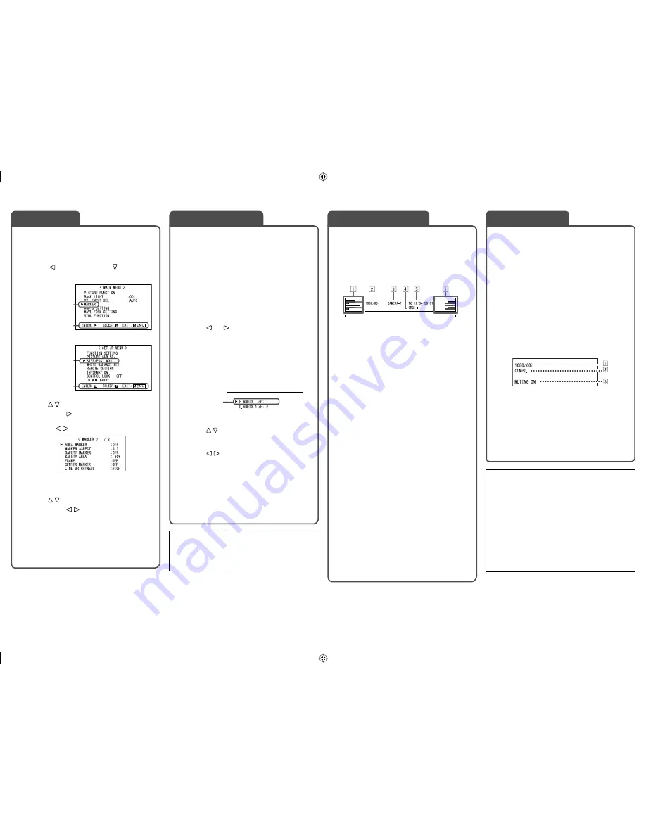
1

  Signal format

•  For the contents displayed, see “On the 

signal format” below and “Available signals” 
on page 9.

2

  Signal format of DVI input

 “DVI INPUT SEL.” on page 10

3

  Setting of “MUTING”

•  Displayed only when muting is activated.

 “ 

4

 MUTING button” on page 6

The monitor displays the information below.
•  Make the setting to display/hide each information 

using the MENU with the exception of 

5

controlled with T.C. button (


r

 on page 6).

•  Select the position of the information display 

(

 “POSITION” in “INFORMATION” on page 

15).

1

  Audio level meter

•  Not displayed when “LEVEL METER ch” is set 

to “OFF.” (

 “AUDIO SETTING” on page 12)

2

  Signal format

•  Displayed when “STATUS DISPLAY” is set to 

“ON.” (

 “INFORMATION” on page 15)

•  For the contents displayed, see “On the 

signal format” below and “Available signals” 
on page 9.

3

  Source name assigned in “CHARACTER SET.”

•  Displayed when “SOURCE ID” is set to “ON.”
•  Displayed in large letters when “STATUS 

DISPLAY” is set to “OFF” or “AUTO.”

 “INFORMATION” on page 15

4

  CRC error indication

• Displayed when “CRC ERROR” is set to “ON.” 

(

 “INFORMATION” on page 15)

•  A red square is displayed when an error 

occurs.

5

  Time code

•  When the input signal includes no time code, 

“TC – –:– –:– –:– –” is displayed.

 “ 

r

 T.C. (time code) button/lamp” on page 6

•  When any information of 

1

2

3

, or 

4


above is displayed while signals come in from 
equipment other than a computer, the picture is 
displayed without overlapping the information 
display area.

  However, the information display will overlap 

with the picture when...
– displaying the picture with higher resolution 

than the resolution of the panel in 1:1 mode.

– “SD4:3 LARGE” setting is “ON.” 

(

 “FUNCTION SETTING” on page 14).

Select audio channels emitted from the speakers 
(L/R) and the AUDIO (MONITOR OUT) (OUT1(L)/
OUT2(R)) terminals, when EMBEDDED AUDIO 
signals come in to the E. AUDIO HD/SD SDI 
terminal (IN1 or IN2) and SDI input (1 or 2) is 
selected.
•  You have to choose a group of selectable audio 

channels before the channel selection (


“E.AUDIO GROUP” in “AUDIO SETTING” on 
page 12).

•  The setting is memorized for each input (SDI 1 

and SDI 2).

1

  Press   or   button when a menu 

is not displayed.

The screen for audio channel selection is 
displayed.
•  The screen for audio channel selection 

automatically disappears in about 30 
seconds after the previous operation.

2

  Press     buttons to select the left 

(L ch) or right (R ch).

3

  Press     buttons to select an 

audio channel.

•  Each time you press the button, the audio 

channel changes according to the settings of 
“E.AUDIO GROUP” (

 “NOTE” on page 12).

4

  Press MENU button.

The screen for audio channel selection 
disappears.

1

  Display the menu.

To display the MAIN MENU

\

 Press MENU button.

To display the SET-UP MENU

\

 Press   button while holding   button.

2

  Press     buttons to select an item, 

then press   button.

•  For some items, adjustments will be made by 

pressing  .

3

  Press     buttons to select an item, 

then press     buttons to make 
adjustments.

4

  Press MENU button to finish the 

menu operation.

•  Pressing MENU button repeatedly 

deactivates the display of the menu.

On the Status Display

Audio Channel Selection

MAIN MENU

SET-UP MENU

Selected item

Selected item

Operation guide

Selected item

Operation guide

Ex.: When “MARKER” in the MAIN 
MENU is selected

Menu Operations

Audio channel selection screen

On the Information Display

On the signal format

The following messages appear depending on the 
type of input signals and their conditions.

When a DVI-D signal protected with HDCP is input

\

 “

*

” (at the end of the indication)

When no video signal comes in

\

 “NO SYNC”

When a noncompliant video signal comes in

\

 “Out of range”

When “COLOR SYSTEM” (

 “FUNCTION 

SETTING” on page 14) is set to “AUTO” and the 
noncompliant composite video signals come in

\

 “OTHERS”

Using the audio level meter

You can check the conditions of the current 
EMBEDDED AUDIO signals in the audio level meter. 
(

 “On the Information Display” on the right,“LEVEL 

METER SETTING” in “AUDIO SETTING” on page 12).

DT-V17L3D_EN3.indd   7

DT-V17L3D_EN3.indd   7

08.6.25   10:29:00 PM

08.6.25   10:29:00 PM

Содержание DT-V17L3D

Страница 1: ...of electric shock Do not remove cover or back No user serviceable parts inside Refer servicing to qualified service personnel RISK OF ELECTRICAL SHOCK DO NOT OPEN The lightning flash with arrowhead symbol within an equilateral triangle is intended to alert the user to the presence of uninsulated dangerous voltage within the product s enclosure that may be of sufficient magnitude to constitute a ri...

Страница 2: ...gs must not be blocked or covered Never push objects of any kind into this product through openings as they may touch dangerous voltage points or short circuit the parts which could result in a fire or electric shock Never spill liquid of any kind on the product Never place anything on the product Placing liquids naked flames cloths paper etc on the product may cause a fire Do not apply any strong...

Страница 3: ...atus When a cart is used use caution when moving the cart apparatus combination to avoid injury from tip over 13 Unplug this apparatus during lightning storms or when unused for long periods of time 14 Refer all servicing to qualified service personnel Servicing is required when the apparatus has been damaged in any way such as power supply cord or plug is damaged liquid has been spilled or object...

Страница 4: ...may fall over Place the monitor on a mat to avoid scratching the table surface Do not lift up the stand when the stand plate is attached to the lower position of the stand body When the battery is attached the stand may not be lifted up depending on the type of the battery To detach the stand CAUTION Lay the monitor on a cloth with the LCD panel facing down to prevent the LCD panel from being dama...

Страница 5: ...ody Stand body Higher position Lower position To prevent an accidental fall Fix the monitor to a wall by using strings Fixing the monitor Attach the hook not provided to the VESA mounting holes on the rear panel use the two holes on the upper side using M4 x 10 mm screws not provided Bind the hooks on the rear panel of the monitor to a wall or a pillar using durable string Hook and screw M4 x 10 m...

Страница 6: ...ally lamp from GREEN or RED TALLY SELECT in FUNCTION SETTING on page 14 and External Control on page 16 NO EFFECT is displayed when you press a button which is not available for the current input or signal format the lamp lights even when the function does not actually work The items controlled by the MAKE system cannot be controlled by the buttons on the front panel REMOTE ON is displayed and the...

Страница 7: ...ing is ON FUNCTION SETTING on page 14 Select audio channels emitted from the speakers L R and the AUDIO MONITOR OUT OUT1 L OUT2 R terminals when EMBEDDED AUDIO signals come in to the E AUDIO HD SD SDI terminal IN1 or IN2 and SDI input 1 or 2 is selected You have to choose a group of selectable audio channels before the channel selection E AUDIO GROUP in AUDIO SETTING on page 12 The setting is memo...

Страница 8: ...ample when turning off the POWER switch the power supply automatically switches to the DC 12 V power supply p DC switch Turns the DC 12 V power on or off You need to press button u on page 6 on the front panel to turn on the monitor after turning on the DC switch The monitor consumes the battery even while the monitor is on standby To save battery life turn off the DC switch q AC IN terminal AC po...

Страница 9: ...20 1200 74 0 60 0 Non interlace 11 720 60p 1280 720 45 0 60 0 Non interlace 12 1080 60p 4 1920 1080 67 5 60 0 Non interlace 13 720 50p 1280 720 37 5 50 0 Non interlace 14 1080 50p 4 1920 1080 56 25 50 0 Non interlace 4 When No 7 10 12 and 14 signals come in thin lines will become obscured because their signal resolution is higher than the screen resolution Non preset signals may not be displayed n...

Страница 10: ...eset Restore the default settings for all the items in PICTURE FUNCTION 1 Memorized for each input BACK LIGHT Adjusts the brightness of the display DVI INPUT SEL When AUTO is selected the format of signals come in to the DVI D HDCP terminal is automatically recognized Normally select AUTO Select MODE1 MODE2 or MODE3 when the picture is not displayed correctly with AUTO DVI D input of the monitor i...

Страница 11: ...ea marker 4 3 14 9 13 9 2 35 1 1 85 1 1 66 1 SAFETY MARKER Activate deactivate the safety marker and select the style of it NOTE SAFETY AREA Adjust the area of the safety marker 80 100 FRAME Displays hides the frame indicating the area of the specified aspect ratio OFF ON CENTER MARKER Displays hides the marker indicating the center position of the picture OFF ON LINE BRIGHTNESS Adjust the brightn...

Страница 12: ...ING 1 Adjust the level meter display for the EMBEDDED AUDIO signals NOTE LEVEL METER ch Select how the audio channels are displayed on the level meter OFF LINE Displays the channels 1 6 at the left of the screen and 7 12 at the right DIVIDE Displays the odd channels at the left of the screen and the even channels at the right BAR TYPE Select the color of the level meter display 3COLORS 3 colors to...

Страница 13: ...ynchronization with signals Item To do Setting value NO SYNC ACTION Select the screen status when no signal is coming in OFF P SAVE power save mode GRAY B gray screen DELAY TIME Select the period until the screen status changes as selected in NO SYNC ACTION after signals stop coming in 30sec 5min 15min LOW LATENCY Activates deactivates the function to shorten the time taken to display the picture ...

Страница 14: ... Adjust the vertical picture position sub menu Display the sub menu which enables you to adjust the items of SIZE POSI ADJ while viewing the actual picture reset Restore the default settings for all the items in SIZE POSI ADJ 2 Memorized for each signal format WHITE BALANCE SET Selects the color temperature and adjusts the drive level and cutoff point of each color R G B Item To do Setting value C...

Страница 15: ...ssigned in CHARACTER SET is displayed on the screen On the Information Display on page 7 OFF ON CHARACTER SET 1 Assign a name to each video source as you like 10 characters at maximum You can also enter a name using the RS 232C system NOTE STATUS DISPLAY Select if the status of the current input and the setting of muting are displayed on the screen On the Status Display on page 7 AUTO OFF ON CRC E...

Страница 16: ...unit SERIAL TYPE setting PARALLEL TYPE setting MAKE TRIGGER terminal MAKE MAKE TRIGGER TRIGGER RS 485 terminal Serial communication RS 485 RS485 1 RS 232C terminal RS 232C RS232C 1 1 For a monitor connected to a personal computer etc select the terminal the equipment is actually connected to For other monitors select RS485 PC etc RS 485 IN or RS 232C RS 485 OUT RS 485 IN RS 485 OUT RS 485 IN RS 48...

Страница 17: ...t to DVI Invalid Valid COMPONENT Changes the input to COMPO Invalid Valid VIDEO Changes the input to VIDEO Invalid Valid A MARKER The area marker indication Off On S MARKER The safety marker indication Off On FRAME Indication of the area of the specified aspect ratio Off On C MARKER The center marker indication Off On MARK SEL Selects the items of MARKER 3 Non R items R items ASPECT Changes the as...

Страница 18: ...ion procedures Basic command list No Commands Functions Data 1 1 B C N 1 Cr Starts communication connection No data 2 1 B C N 0 Cr Terminates communication termination No data 3 1 B I D S E T x x 2 Cr Assigns the control ID 01 99 4 1 B I D R E T Cr Initializes the control ID No data 5 1 B I D D S P x x 2 Cr Displays hides the ID 00 Hide 01 Display 6 1 B I D C H K x x 2 Cr Flashes hides the selecte...

Страница 19: ...ayed for a long time it may remain indistinctly on the screen after the picture has changed Though the remaining picture will disappear after a while there may be a case that it remains for a long period depending on the length of time the still image was displayed for This is due to the characteristics of the LCD display and is not a malfunction Red spots blue spots and green spots on the panel s...

Страница 20: ... the screen such as uneven color discoloration scratches be careful about the following Do not paste or stick anything using any glues or adhesive tapes Do not write anything on the screen Do not strike the screen with a hard object Avoid condensation on the screen Do not wipe the screen with solvent such as alcohol thinner or benzine Do not wipe the screen forcefully Wipe stains off the screen wi...

Страница 21: ... stand 304 mm 12 without the stand Depth 199 mm 7 7 8 with the stand 86 mm 3 1 2 without the stand Weight 7 kg 15 5 lbs with the stand 5 3 kg 11 7 lbs without the stand Accessories AC power cord Power cord holder x 1 Screw x 2 for power cord holder Ferrite core x 1 for external battery 7 Input output terminals Video VIDEO Input output of composite signal 1 line BNC connector x 2 1 V p p 75 Ω The i...

Страница 22: ... Unit mm inch Front view Side view Rear view 100 199 7 7 8 240 9 1 2 VESA mounting holes Size 4 M4 depth 10 mm 100 115 1 5 1 16 395 15 5 8 304 12 344 8 13 5 8 309 5 12 1 4 86 3 1 2 40 1 5 8 34 1 3 8 DT V17L3D_EN3 indd 22 DT V17L3D_EN3 indd 22 08 6 25 10 29 21 PM 08 6 25 10 29 21 PM ...

Страница 23: ...DT V17L3D_EN_cover34 indd 1 DT V17L3D_EN_cover34 indd 1 08 5 19 8 49 11 PM 08 5 19 8 49 11 PM ...

Страница 24: ... 2008 Victor Company of Japan Limited 0708STH MW VP DT V17L3D MULTI FORMAT LCD MONITOR DT V17L3D_EN_cover34 indd 2 DT V17L3D_EN_cover34 indd 2 08 5 19 8 49 12 PM 08 5 19 8 49 12 PM ...

Отзывы: