JVC DT-V17L2D Скачать руководство пользователя страница 14

13

ENGLISH

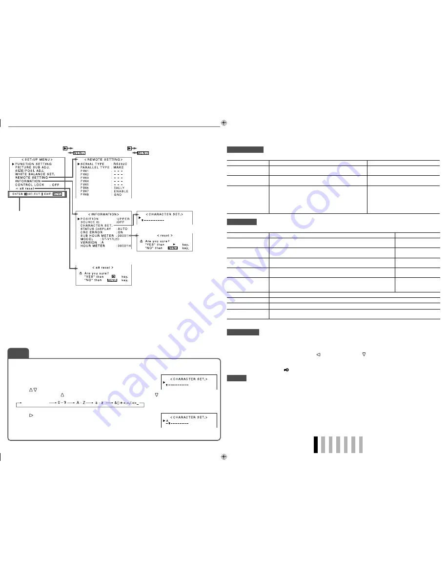
Setting of “CHARACTER SET.”

Assign a name for each video source following the steps below.

1

  Change the input to one that you want to assign a video source name for.

2

  Select “CHARACTER SET.”

3

  Press     buttons to select the first character.

•  Each time you press   button, the character changes as follows. Press   button to reverse the order.

4

  Press   button to move the arrow to the next.

•  The characters entered before moving the arrow are memorized.

5

  Repeat steps 

3

 and 

4

 (10 characters at maximum).

6

  Press MENU button to store the name.

Operation guide

Shows the buttons for 
each operation.

•  The menu automatically disappears in about 30 seconds after the previous operation.
•  Some items may not appear on the menu depending on the input or the input signal.
•  The items controlled by the MAKE system do not appear on the menu.

REMOTE SETTING

Setting for the external control

Item

To do

Setting value

SERIAL TYPE

Select the input terminal used for external control by 
serial communication.

RS232C, RS485

PARALLEL TYPE

Select the external control method for the MAKE/
TRIGGER terminal.

MAKE, TRIGGER, SET

PIN1, PIN2, PIN3, 
PIN4, PIN5

Assign the control functions to the pins of the MAKE/
TRIGGER terminal.
•  Assign a function to each pin terminal by selecting 

“SET” in “PARALLEL TYPE.” (The functions are 
assigned for “PIN6” – “PIN8” and you cannot 
change the assignment of these functions.)

COLOR OFF, ASPECT, A.MARKER, 
S.MARKER, TIME CODE, 1:1, SCR 
CHECK, I/P MODE, SDI 1, SDI 2, DVI, 
COMPONENT, VIDEO, TALLY SEL, 
SOURCE ID, MUTING, MARK.SEL, 
L.METER, STATUS, – – – (no function)

INFORMATION

Setting for the information display of the monitor

Item

To do

Setting value

POSITION

Select the position to show the information display (

 “About the 

Information Display” on page 7).

UPPER, LOWER

SOURCE ID

Select if the name assigned in “CHARACTER SET.” is displayed on 
the screen (

 “About the Information Display” on page 7).

OFF, ON

CHARACTER SET.

*

1

Assign a name to each video source as you like (10 characters at 
maximum). You can also enter a name using the RS-232C system.

 “NOTE”

STATUS DISPLAY

Select if the status of the current input and the setting of muting are 
displayed on the screen (

 “About the Status Display” on page 7).

AUTO, OFF, ON

CRC ERROR

Select if the CRC error indication for the input HD SDI signal is 
displayed on the screen (

 “About the Information Display” on page 

7).

OFF, ON

SUB HOUR METER

Display the hours of use (unit: hour). You can reset this item.

MODEL

Display the model name of the monitor.

VERSION

Display the version of the monitor.

HOUR METER

Display the total hours of use (unit: hour). This item is used for maintenance of the monitor. You 
cannot reset this item.

*

1

 Memorized for each input.

CONTROL LOCK

Turns on (or off) the control lock function to disable the buttons on the front panel.
•  The following operations are available even when this function is activated.

– Turning on/off (on standby) the monitor
– Displaying the SET-UP MENU (by pressing   button while pressing   button) and turning “CONTROL LOCK” 

to “OFF”

– Operating the monitor by an external control 

  If you try other operations, “ 

Control lock on!” appears on the screen.

all reset

Restores all the settings and adjustments of the monitor to the default.
•  “HOUR METER” and the settings done by using the adjustment knobs on the front panel will not be reset.
•  When you operate the monitor with the AC power supply, the monitor is turned off (on standby) then turned 

on automatically. When you operate the monitor with the DC 12 V power supply, the monitor is turned off (on 
standby).

Space

(

 “External Control” on pages 14 and 15)

Setting value:

 OFF, ON

NOTE

DT-V17L2D_EA_EN_R.indd   13

DT-V17L2D_EA_EN_R.indd   13

07.9.14   7:01:49 PM

07.9.14   7:01:49 PM

Содержание DT-V17L2D

Страница 1: ...UCTIONS ISTRUZIONI MANUAL DE INSTRUCCIONES ИHCТРУKЦИЯ ПО ЭКСПЛУАТАЦИИ MULTI FORMAT LCD MONITOR MULTI FORMAT LCD MONITOR MONITEUR LCD MULTI FORMAT MONITOR LCD MULTIFORMATO MONITOR LCD MULTIFORMATO МУЛЬТИФОРМАТНЫЙ ЖК МОНИТОР ESPAÑOL ITALIANO ENGLISH DEUTSCH FRANÇAIS РУССКИЙ ...

Страница 2: ...e risk of electric shock Do not remove cover or back No user serviceable parts inside Refer servicing to qualified service personnel RISK OF ELECTRICAL SHOCK DO NOT OPEN The lightning flash with arrowhead symbol within an equilateral triangle is intended to alert the user to the presence of uninsulated dangerous voltage within the product s enclosure that may be of sufficient magnitude to constitu...

Страница 3: ...overload wall outlets extension cords or convenience receptacles on other equipment as this can result in a risk of fire or electric shock Use only the accessory cord designed for this product to prevent shock Slots and openings in the cabinet are provided for ventilation These ensure reliable operation of the product and protect it from overheating These openings must not be blocked or covered Ne...

Страница 4: ...netic waves or magnetism are near the audio cable or the signal cable the sound or the picture will contain noise In such cases please keep the cable away from the sources of the disturbance European Union only Cabinet To avoid the deterioration or damages of the cabinet such as its paint s peeling away be careful about the following Do not wipe the cabinet using solvent such as alcohol thinner or...

Страница 5: ...rom being damaged CAUTION Be careful not to pinch your fingers in the gap between the monitor and the stand When the stand plate is attached to the lower position of the stand body To adjust the stand height on page 5 you cannot tilt the monitor downward About 6 About 6 CAUTION When lifting up the stand lay the monitor on a cloth with the LCD panel facing down to prevent the LCD panel being damage...

Страница 6: ...detaching the stand from the monitor For detaching the stand see To detach the stand on page 4 Stand body Higher position Lower position To prevent an accidental fall Fix the monitor to a wall by using strings Fixing the monitor Attach the hook not provided to the VESA mounting holes on the rear panel use the two holes on the upper side using M4 x 10 mm screws not provided Bind the hooks on the re...

Страница 7: ...ondition It is recommended to replace the battery when the lamp turns to orange Tally lamp This lamp is controlled by the tally function of the MAKE TRIGGER terminal TALLY SELECT in FUNCTION SETTING on page 12 and External Control on page 14 NO EFFECT is displayed when you press a button which is not available for the current input or signal format the lamp lights even when the function does not a...

Страница 8: ... CRC ERROR in INFORMATION on page 13 A red square is displayed when an error occurs When any information of 1 2 3 or 5 above is displayed while signals come in from equipment other than a computer the picture is displayed without overlapping the information display area However when displaying the picture with higher resolution than the resolution of the panel in 1 1 mode the information display w...

Страница 9: ... HDCP terminal on this monitor does not conform to the HDMI standard 9 DC IN 12V terminal DC 12 V maximum DC 17 V power input connector While using both the AC and DC 12 V power supply AC power supply is preferentially used If the AC power supply is cut off for example when unplugging the AC power cord the power supply automatically switches to the DC 12 V power supply p DC switch Turns the DC 12 ...

Страница 10: ...920 1200 74 0 60 0 Non interlace 10 720 60p 1280 720 45 0 59 9 60 0 Non interlace 11 1080 60p 5 1920 1080 67 5 67 4 59 9 60 0 Non interlace 5 When signals of No 7 9 and 11 come in thin lines will become obscured because their signal resolution is higher than the screen resolution 1440 x 900 Non preset signals may not be displayed normally even if its frequency is within the acceptable range Horizo...

Страница 11: ...isplayed by using AREA MARKER or SAFETY MARKER button or external control Select either non R items or R items to activate by using external control External Control on page 14 When a picture is displayed in 4 3 aspect ratio the safety marker for the 4 3 area is displayed To display the safety marker for the area of a picture displayed in 16 9 aspect ratio hide the area marker 1 Memorized for each...

Страница 12: ... W 100 white REFERENCE LEVEL Select the standard input level indicated on the level meter 20dB 18dB OVER LEVEL Select the input level s lower limit indicated in red for the 3COLORS display 10dB 8dB 6dB 4dB 2dB BAR BRIGHTNESS Select the brightness of the level meter LOW HIGH SYNC FUNCTION Setting for the synchronization with signals Item To do Setting value NO SYNC ACTION Select the screen status w...

Страница 13: ...icture position V SIZE 2 Adjust the vertical picture size V POSITION 2 Adjust the vertical picture position sub menu Display the sub menu which enables you to adjust the items of SIZE POSI ADJ while viewing the actual picture reset Restore the default settings for all the items in SIZE POSI ADJ WHITE BALANCE SET Selects the color temperature and adjusts the drive level and cutoff point of each col...

Страница 14: ... page 7 UPPER LOWER SOURCE ID Select if the name assigned in CHARACTER SET is displayed on the screen About the Information Display on page 7 OFF ON CHARACTER SET 1 Assign a name to each video source as you like 10 characters at maximum You can also enter a name using the RS 232C system NOTE STATUS DISPLAY Select if the status of the current input and the setting of muting are displayed on the scr...

Страница 15: ...tem SERIAL TYPE setting PARALLEL TYPE setting MAKE TRIGGER terminal MAKE MAKE TRIGGER TRIGGER RS 485 terminal Serial communication RS 485 RS485 1 RS 232C terminal RS 232C RS232C 1 1 On the monitor connected to the personal computer etc select the terminal the equipment is actually connected to On other monitors select RS485 Control priority is as follows MAKE TRIGGER serial communication and butto...

Страница 16: ...mand ID Function Data Cr 0DH Header Operation commands from the personal computer etc For details see Basic command list on the right Reference commands from the personal computer etc Status returns from the monitor To start communication send the connection command from the personal computer etc To terminate the communication send the termination command from the personal computer etc Example of ...

Страница 17: ...o sure method to solve this problem 6 9 12 Some items do not appear on the menu The items which are not available for the current input or the current input signal are not displayed on the menu Change the input or the input signal The items controlled by the MAKE system do not appear on the menu 14 Buttons on the monitor do not work Set CONTROL LOCK in the SET UP MENU to OFF 13 The following are n...

Страница 18: ...tand 304 mm without the stand Depth 243 mm with the stand 86 mm without the stand Weight 8 1 kg with the stand 5 2 kg without the stand Accessories AC power cord x 2 Power cord holder x 1 Screw x 2 for power cord holder Ferrite core x 1 for external battery Notice on transportation This monitor is precision equipment and needs dedicated packing material for transportation Never use any packing mat...

Страница 19: ... mounting holes 4 M4 depth 10 mm 304 100 115 344 6 309 6 at the higher position at the lower position 7 Dimensions Unit mm 1 5 64 Front view Side view Rear view DT V17L2D_EA_EN_R indd 18 DT V17L2D_EA_EN_R indd 18 07 9 14 7 01 53 PM 07 9 14 7 01 53 PM ...

Страница 20: ... 2007 Victor Company of Japan Limited 0907MKH MW VP ...

Отзывы: