(No.MB286)1-7
SECTION 3
DISASSEMBLY
3.1
Main body section
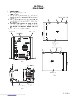
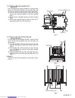
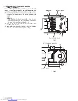
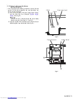
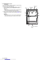
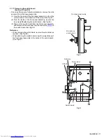
3.1.1 Removing the side panels L/R
(See Figs.1 to 4)
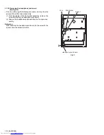
(1) From the back side of the main body, remove the four
screws
A
attaching the side panels L/R to the rear panel.
(See Fig.1.)
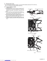
(2) From the bottom side of the main body, remove the two
screws
B
attaching the side panels L/R to the bottom chas-
sis. (See Fig.2.)
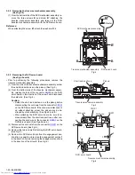
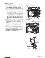
(3) From the both sides of the main body, release the engage-
ment sections (
a
,
b
) of the side panels L/R from the top
cover assembly in the direction of the arrow. (See Figs.3
and 4.)
(4) Remove the side panels L/R toward this side.
Fig.1
Fig.2
Fig.3
Fig.4
Side panel R
Side panel L
Rear panel
A
A
Side panel L
B
B
Bottom chassis
Side panel R
Top cover assembly
a
a
a
Side panel R
b
b
b
Side panel L
Top cover assembly
Содержание CA-UXP550
Страница 38: ...1 38 No MB286 SECTION 5 TROUBLESHOOTING This service manual does not describe TROUBLESHOOTING ...
Страница 39: ... No MB286 1 39 ...
Страница 79: ...3 21 MEMO ...


