(No.MB662<Rev.003>)1-15
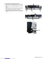
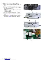
3.1.9 Removing the Rear panel (See Fig.20)
(1) Remove the two screws
S
attaching the Rear panel.
Fig.20
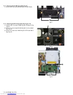
3.1.10 Removing the Power board (See Fig.21)
(1) Disconnect the power cord connected to connector
CN1
of
the Power board.
(2) Remove the five screws
T
attaching the Power board.
Fig.21
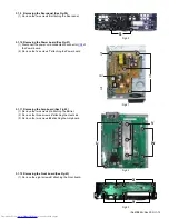
3.1.11 Removing the Amp board (See Fig.22)
(1) Remove the two screws
U
attaching the Barrier.
(2) Remove the three screws
V
attaching the Heat sink.
(3) Remove the two screws
W
attaching the Amp board.
Fig.22
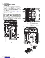
3.1.12 Removing the Front board (See Fig.23)
(1) Remove the eight screws
X
attaching the Front board.
Fig.23
S
T
T
T
CN1
U
V
W
X
X
Содержание CA-NXF3
Страница 45: ... M E M O ...
Страница 70: ...3 25 MEMO ...


