background image

(No.YA057)1-3

SECTION 1

PRECAUTION

1.1

SAFETY PRECAUTIONS

(1) The design of this product contains special hardware, many

circuits and components specially for safety purposes. For
continued protection, no changes should be made to the original
design unless authorized in writing by the manufacturer.
Replacement parts must be identical to those used in the original
circuits. Service should be performed by qualified personnel only.

(2) Alterations of the design or circuitry of the products should not be

made. Any design alterations or additions will void the
manufacturer's warranty and will further relieve the manufacturer
of responsibility for personal injury or property damage resulting
therefrom.

(3) Many electrical and mechanical parts in the products have special

safety-related characteristics. These characteristics are often not
evident from visual inspection nor can the protection afforded by them
necessarily be obtained by using replacement components rated for
higher voltage, wattage, etc. Replacement parts which have these
special safety characteristics are identified in the parts list of Service
manual. 

Electrical components having such features are

identified by shading on the schematics and by (   ) on the
parts list in Service manual

. The use of a substitute replacement

which does not have the same safety characteristics as the
recommended replacement part shown in the parts list of Service
manual may cause shock, fire, or other hazards.

(4)

Use isolation transformer when hot chassis.

The chassis and any sub-chassis contained in some products are
connected to one side of the AC power line. An isolation
transformer of adequate capacity should be inserted between the
product and the AC power supply point while performing any
service on some products when the HOT chassis is exposed.

(5)

Don't short between the LIVE side ground and ISOLATED (NEU-
TRAL) side ground or EARTH side ground when repairing.


Some model's power circuit is partly different in the GND. The differ-
ence of the GND is shown by the LIVE : (   ) side GND, the ISOLAT-
ED (NEUTRAL) : (   ) side GND and EARTH : (   ) side GND. 
Don't short between the LIVE side GND and ISOLATED (NEUTRAL)
side GND or EARTH side GND and never measure the LIVE side
GND and ISOLATED (NEUTRAL) side GND or EARTH side GND at
the same time with a measuring apparatus (oscilloscope etc.). If
above note will not be kept, a fuse or any parts will be broken.

(6) If any repair has been made to the chassis, it is recommended that

the B1 setting should be checked or adjusted (See B1 POWER
SUPPLY check).

(7) The high voltage applied to the picture tube must conform with that

specified in Service manual. Excessive high voltage can cause an
increase in X-Ray emission, arcing and possible component
damage, therefore operation under excessive high voltage
conditions should be kept to a minimum, or should be prevented.
If severe arcing occurs, remove the AC power immediately and
determine the cause by visual inspection (incorrect installation,
cracked or melted high voltage harness, poor soldering, etc.). To
maintain the proper minimum level of soft X-Ray emission,
components in the high voltage circuitry including the picture tube
must be the exact replacements or alternatives approved by the
manufacturer of the complete product.

(8) Do not check high voltage by drawing an arc. Use a high voltage

meter or a high voltage probe with a VTVM. Discharge the picture
tube before attempting meter connection, by connecting a clip lead
to the ground frame and connecting the other end of the lead
through a 10k

 2W resistor to the anode button. 

(9) When service is required, observe the original lead dress. Extra

precaution should be given to assure correct lead dress in the high
voltage circuit area. Where a short circuit has occurred, those
components that indicate evidence of overheating should be
replaced. Always use the manufacturer's replacement
components.

(10)

Isolation Check (Safety for Electrical Shock Hazard) 

After re-assembling the product, always perform an isolation
check on the exposed metal parts of the cabinet (antenna
terminals, video/audio input and output terminals, Control knobs,
metal cabinet, screw heads, earphone jack, control shafts, etc.) to
be sure the product is safe to operate without danger of electrical
shock.

a)

Dielectric Strength Test


The isolation between the AC primary circuit and all metal parts
exposed to the user, particularly any exposed metal part having a
return path to the chassis should withstand a voltage of 1100V AC
(r.m.s.) for a period of one second.
(. . . . Withstand a voltage of 1100V AC (r.m.s.) to an appliance rat-
ed up to 120V, and 3000V AC (r.m.s.) to an appliance rated 200V
or more, for a period of one second.) This method of test requires
a test equipment not generally found in the service trade.

b)

Leakage Current Check


Plug the AC line cord directly into the AC outlet (do not use a line
isolation transformer during this check.). Using a "Leakage
Current Tester", measure the leakage current from each exposed
metal part of the cabinet, particularly any exposed metal part
having a return path to the chassis, to a known good earth ground
(water pipe, etc.). Any leakage current must not exceed 0.5mA AC
(r.m.s.). 
However, in tropical area, this must not exceed 0.2mA AC (r.m.s.). 

Alternate Check Method

Plug the AC line cord directly into the AC outlet (do not use a
line isolation transformer during this check.). Use an AC
voltmeter having 1000

 per volt or more sensitivity in the

following manner. Connect a 1500

 10W resistor paralleled by

a 0.15

µ

F AC-type capacitor between an exposed metal part and

a known good earth ground (water pipe, etc.). Measure the AC
voltage across the resistor with the AC voltmeter. Move the
resistor connection to each exposed metal part, particularly any
exposed metal part having a return path to the chassis, and
measure the AC voltage across the resistor. Now, reverse the
plug in the AC outlet and repeat each measurement. Any
voltage measured must not exceed 0.75V AC (r.m.s.). This
corresponds to 0.5mA AC (r.m.s.). 
However, in tropical area, this must not exceed 0.3V AC
(r.m.s.). This corresponds to 0.2mA AC (r.m.s.).

(11)

High voltage hold down circuit check.

After repair of the high voltage hold down circuit, this circuit shall
be checked to operate correctly.See item 

"How to check the high

voltage hold down circuit"

.

AC VOLTMETER
(HAVING 1000 /V,
OR MORE SENSITIVITY)

PLACE THIS PROBE
ON EACH EXPOSED
METAL PART

1500  10W

0.15 F AC-TYPE

GOOD EARTH GROUND

PWB

White line side

WHT

PW

POWER CORD 
REPLACEMENT WARNING.

Connecting the white line side of power
cord to "WHT" character side.

A         V

This mark shows a fast 
operating fuse, the 
letters indicated below
show the rating.

Содержание AV-32F475/Y

Страница 1: ...AN LIMITED No YA057 2004 3 COLOR TELEVISION YA057 2004 3 AV 32F475 Y AV 32F475 Z AV 32F485 Y AV 32F485 Z TABLE OF CONTENTS 1 PRECAUTION 1 3 2 SPECIFIC SERVICE INSTRUCTIONS 1 4 3 DISASSEMBLY 1 6 4 ADJUSTMENT 1 12 5 TROUBLE SHOOTING 1 28 BASIC CHASSIS GJ4 ...

Страница 2: ...nels Intermediate Frequency Video IF Sound IF 45 75 MHz 41 25 MHz 4 5MHz Color Sub Carrier 3 58 MHz Power Input AC120V 60Hz Power Consumption 160W Picture Tube Visible size 80cm 32 Measured diagonally H 65 6cm W 49 6cm High Voltage 31 4kV 1 3kV at Zero beam current Speaker 6 5cm 13cm 2 1 2 5 Oval type 2 Audio Power Output 7 5W 7 5W 9W 9W Antenna Terminal VHF UHF F type connector 75 Ω unbalanced Vi...

Страница 3: ... the manufacturer of the complete product 8 Do not check high voltage by drawing an arc Use a high voltage meter or a high voltage probe with a VTVM Discharge the picture tube before attempting meter connection by connecting a clip lead to the ground frame and connecting the other end of the lead through a 10kΩ 2W resistor to the anode button 9 When service is required observe the original lead dr...

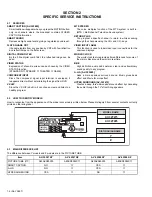
Страница 4: ...g through the channels using the CH and CH keys VIDEO INPUT LABEL This function is used to label video input connections for the onscreen displays WORLD CLOCK The world clock feature provides time differences for some of the major cities around the world in real time BBE High definition audio adds natural clear and extraordinary sound quality to any program A H S AV 32F485 Adds a more spacious sur...

Страница 5: ...lter IC5201 10 AGC_MUTE O AGC muting for tuner when channel select Muting H 38 YC_Vcc 5V for video process circuit 11 uP_VVSS GND 39 R_OUT O R signal 12 TV_HGND GND 40 G_OUT O G signal 13 FBP_SCP I Flyback pulse H pulse 41 B_OUT O B signal 14 HOUT O H drive oscillation 42 RGB_Vcc 9V for RGB process circuit 15 H_Vcc 9V for H oscillation start 43 IK_IN I Not used 16 HAFC_1 H AFC filter 44 TV_DGND GN...

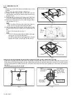
Страница 6: ...VING THE LED POWER SW PWB Remove the REAR COVER 1 Remove the 2 screws E 2 Withdraw the LED POWER SW PWB toward you If necessary remove the wire clamp connector etc 3 1 6 REMOVING THE FRONT CONTROL PWB Remove the REAR COVER 1 Remove the 2 screws F 2 Withdraw the FRONT CONTROL PWB toward you If necessary remove the wire clamp connector etc 3 1 7 CHECKING THE CHASSIS To check the PW Board from back s...

Страница 7: ... No YA057 1 7 Fig 1 A REAR COVER C D E F FRONT CONTROL PWB CRT SOCKET PWB LED POWER SW PWB SPEAKER SPEAKER HOLDER FRONT CABINET B CLAW CLAW AV SELECTOR PWB MAIN PWB AV TERMINAL BOARD POWER CORD ...

Страница 8: ...ting steps The CRT change table should preferably be smaller that the CRT surface and its height be about 35cm Fig 3 Fig 4 Fig 5 COATING OF SILICON GREASE FOR ELECTRICAL INSULATION ON THE CRT ANODE CAP SECTION Subsequent to replacement of the CRT and HV transformer or repair of the anode cap etc by dismounting them be sure to coat silicon grease for electrical insulation as shown in Fig 6 Wipe aro...

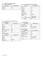
Страница 9: ... table Where these do not agree refer to the OPERATING INSTRUCTIONS USER S GUIDE and set the items as described 6 SERVICE MODE setting Verify what to set in the SERVICE MODE and set whatever is necessary Fig 1 Refer to the SERVICE ADJUSTMENT for setting 3 2 2 SERVICE MODE SETTING ITEMS Fig 1 Setting items Settings Item No 1 V C Video setting Adjust S01 S48 2 DEF Deflection setting Adjust D01 D33 3...

Страница 10: ...ATER PRO OFF VIDEO STATUS DYNAMIC ASPECT 4 3 SOUND A H S OFF AV 32F485 HYPER SURROND OFF AV 32F475 BBE ON Setting item Setting position TINT 0 COLOR 0 PICTURE 8 BRIGHT 0 DETAIL 8 COLOR TEMPERATURE HIGH NOISE MUTING ON VSM ON Setting item Setting position BASS 0 TREBLE 0 BALANCE 0 MTS STEREO SMART SOUND OFF Setting item Setting position SET CLOCK OFF ON OFF TIMER OFF WORLD CLOCK Refer to OPERATING ...

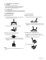
Страница 11: ...the tweezers and remove the chip part Transistors diodes variable resistors etc 1 Apply extra solder to each lead 2 As shown in the figure push the part with tweezers and alternately melt the solder at each lead Shift and remove the chip part NOTE After removing the part remove remaining solder from the pattern 2 How to install Chip parts Resistors capacitors etc 1 Apply solder to the pattern as i...

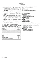
Страница 12: ...tems of this service adjustment 4 2 PRESET SETTING BEFORE ADJUSTMENTS Unless otherwise specified in the adjustment items preset the following functions with the REMOTE CONTROL UNIT 4 3 MEASURING INSTRUMENT AND FIXTURES DC voltmeter or digital voltmeter Oscilloscope Frequency counter Signal generator Pattern generator NTSC TV audio multiplex signal generator Remote control unit 4 4 ADJUSTMENT ITEMS...

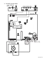
Страница 13: ...1 LOWER SCREEN S1401 DOWN UP IC201 CN004 MAIN PWB PW F901 DEG MEMORY IC TUNER 5A V CENTER SW V CENTER SW VCO VCO FRONT TOP CRT SOCKET PWB SOLDER SIDE TP E CN3005 CN3004 TP R TP B FRONT LED POWER SW PWB FRONT CONTROL PWB FRONT CN6007 CN6006 B 1 TP E 2 X RAY2 3 X RAY1 4 NC 5 TP 91 B CN5006 CN005 C 1 5 TO SPEAKER POWER POWER LED REMOCON ...

Страница 14: ...IGHT 5 3L Y C LYC Fixed value LYC01 1 V C S 2 DEF D 3 SOUND A 4 OTHERS F 5 3L Y C LYC 7 LOW LIGHT 8 HIGH LIGHT 9 VCO 11 I2C BUS 12 SYSTEM SYS SELECT BY OPERATE BY EXIT BY EXIT SERVICE MENU BRIGHT 7 LOW LIGHT SUB MENU MAIN MENU 12 SYSTEM SYS Fixed value SYS01 VIDEO IN 11 I2C BUS Fixed value I2C BUS ON 9 VCO 8 HIGH LIGHT TOO HIGH GOOD TOO LOW SYNC YES AFC ON FINE 0 ...

Страница 15: ...OW TO EXIT THE SERVICE MODE Press the EXIT key to exit the SERVICE MODE 1 V C S This sets the setting values of the VIDEO circuit 2 DEF D This sets the setting values of the DEFLECTION circuit 3 SOUND A This sets the setting values of the AUDIO circuit 4 OTHERS F This sets the setting values of the factory settings Do not adjust 6 3L Y C LYC This sets the setting values of the 3 line YC separation...

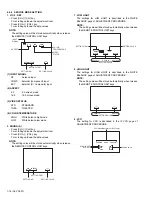
Страница 16: ...when release the REMOTE CONTROL UNIT keys 8 HIGH LIGHT The settings for HIGH LIGHT is described in the WHITE BALANCE page of ADJUSTMENT PROCEDURE NOTE The setting value will be stored automatically when release the REMOTE CONTROL UNIT keys 9 VCO The setting for VCO is described in the IF VCO page of ADJUSTMENT PROCEDURE RF Antenna input COMP External component input EXT External S Composite input ...

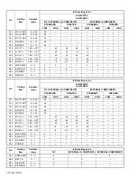
Страница 17: ...TERNAL S COMPOSITE EXTERNAL COMPONENT STANDARD THEATER STANDARD STANDARD 4 3 16 9 4 3 4 3 4 3 S01 BRIGHT 0 127 64 S02 PICTURE 0 127 60 S03 COLOR 0 127 48 45 S04 TINT 0 127 50 72 S05 DETAIL 0 63 35 40 40 S06 BRIGHT 32 32 0 1 4 2 S07 PICT 32 32 8 10 0 0 S08 COLOR 32 32 0 3 1 S09 TINT 32 32 0 3 9 S10 DETAIL 32 32 0 No Setting item Variable range Initial setting value AV 32F475 Z AV 32F485 Z RF EXTERN...

Страница 18: ...S24 DCRSW 0 1 1 1 No Setting item Variable range Initial setting value AV 32F475 Z AV 32F485 Z RF EXTERNAL S COMPOSITE EXTERNAL COMPONENT STANDARD THEATER STANDARD THEATER LOW HIGH LOW HIGH LOW HIGH LOW HIGH S11 R CUT OFF 0 255 30 S12 G CUT OFF 0 255 30 S13 B CUT OFF 0 255 30 S14 R DRIVE 0 127 64 S15 B DRIVE 0 127 64 S16 R CUT 128 127 0 0 0 0 S17 G CUT 128 127 0 0 0 0 S18 B CUT 128 127 0 0 0 0 S19...

Страница 19: ...VIDEO SW 0 3 3 S32 CMP ABCL 0 1 0 S33 OSD ABL 0 1 0 S34 OSD CONT 0 63 8 S35 SUB CONT 0 15 5 S36 ABL GAIN 0 3 0 S37 ABL PNT 0 3 3 S38 Y GAMMA 0 3 1 S39 Y MUTE 0 1 0 S40 SVM GAIN 0 3 3 S41 SVM PH 0 3 2 S42 WPL 0 1 0 S43 COL GMM 0 1 0 S44 V1 GAIN 0 7 4 S46 VMOFF DE 128 127 3 S47 APC CLK 0 1 1 S48 PIP ADJ 0 15 8 ...

Страница 20: ... 32 D10 V CENT 128 127 0 0 D11 V S CORR 0 15 9 9 8 8 D12 V S CO 128 127 0 0 D13 V LIN 0 15 10 10 8 8 D14 V LIN 128 127 0 0 D15 H SIZE 0 63 49 49 28 28 D16 H SIZE 128 127 0 0 D17 WVMT TOP 0 3 0 1 0 0 1 0 D18 WVMT BTM 0 3 0 1 0 0 1 0 D19 EWCR TOP 0 31 14 14 11 11 D20 EWCR T 128 127 0 0 D21 EWCR BTM 0 31 16 16 11 11 D22 EWCR B 128 127 0 0 D23 EW PARA 0 63 35 35 31 31 D24 EW PARA 128 127 0 13 D25 V EH...

Страница 21: ...128 127 32 F16 VM DAT E 0 1 1 F17 XDSID TM 0 255 15 F18 FM TRAP 0 1 0 No Setting item Variable range Initial setting value LYC01 MODE 0 7 4 LYC02 VENH 0 7 1 LYC03 PDSOFF 0 1 0 LYC04 CB 0 1 0 LYC05 VNLR 0 15 2 LYC06 GSEL0 0 1 0 LYC07 GSEL1 0 1 1 LYC08 COR 0 3 0 LYC09 TRAP 0 1 1 LYC10 CHTRAP 0 1 0 LYC11 CBPF 0 1 0 LYC12 ENHOFF 0 1 0 No Setting item Variable range Initial setting value AV 32F475 AV 3...

Страница 22: ... normal picture is displayed on the screen HVT HEATER 4 CONNECTOR S1 3 2 1 B1 4 5 Item Measuring instrument Test point Adjustment part Description IF VCO Remote control unit 9 VCO CW transf T111 MAIN PWB It must not adjust without inputting the RF signal 1 Receive the broadcast 2 Select 9 VCO from the SERVICE MODE 3 Set the AFC to OFF and FINE to 0 4 Confirm that the color change from TOO HIGH to ...

Страница 23: ...ated within 85 95 range When vertical linearity is not even adjust vertical linearity by D13 V LIN and D11 VS CORR V SIZE V POSITION 16 9 Signal generator Remote control unit 2 DEF D D08 V SIZE D14 V LIN V SIZE V POSITION 4 3 adjustment should be finished 1 Receive a black and white signal color off 2 Select 16 9 mode 3 Confirm that the width of V BLANKING is equal to adjustment value B 4 If the a...

Страница 24: ...n by D19 EWCR TOP and D21 EWCR BTM H POSITION H SIZE SIDE PIN 16 9 Signal generator Remote control unit 2 DEF D D16 H SIZE D04 H POSI D24 EW PARA D20 EWCR T D22 EWCR B V SIZE V POSITION adjustment should be finished H SIZE H POSITION SIDE PIN adjustment should be finished Regular size 4 3 1 Receive the cross hatch signal 2 Select 16 9 mode 3 Confirm both sides of cross hatch to be the adjustment v...

Страница 25: ...t is displayed becomes white using the 4 9 keys 10 Turn the SCREEN VR until the single horizontal line is displayed faintly 11 Press the 2 key to cancel the single horizontal line mode 12 Return to the main menu in SERVICE MODE 13 Select the 1 V C S from the SERVICE MODE 14 Adjust the BRIGHT level to become the black component shines white slightly by S01 15 Confirm that whether the color ingredie...

Страница 26: ... the initial setting value of the S01 5 If the brightness is not the best with the initial setting value make fine adjustment of the S01 until you get the optimum brightness SUB CONTRAST Remote control unit 1 V C S S02 PICTURE 1 Receive the any broadcast 2 Select the 1 V C S from the SERVICE MODE 3 Select S02 PICTURE 4 Set the initial setting value of the S02 5 If the contrast is not the best with...

Страница 27: ...generator to the antenna terminal 2 Connect an oscilloscope to R OUT pin of the AUDIO OUT and display one cycle portion of the 300Hz signal 3 Select the 3 SOUND A from the SERVICE MODE 4 Select the A02 LOW SEP 5 Set the initial setting value of the A02 6 Adjust the A02 so that the stroke element of the 300Hz signal will become minimum 7 Change the connection of the oscilloscope to L OUT pin of the...

Страница 28: ...1 28 No YA057 SECTION 5 TROUBLE SHOOTING This service manual does not describe TROUBLESHOOTING ...

Страница 29: ...pacitor MF R Metal Film Resistor MF CAP Metalized Film Capacitor MG R Metal Glazed Resistor MM CAP Metalized Mylar Capacitor MP R Metal Plate Resistor MP CAP Metalized Polystyrol Capacitor OM R Metal Oxide Film Resistor PP CAP Polypropylene Capacitor CMF R Coating Metal Film Resistor PS CAP Polystyrol Capacitor UNF R Non Flammable Resistor TF CAP Thin Film Capacitor CH V R Chip Variable Resistor M...

Страница 30: ... SELECTOR P W BOARD ASS Y SGJ 5506A M2 3 15 FRONT CONTROL P W BOARD ASS Y SGJ 6506A M2 3 15 LED POWER SW P W BOARD ASS Y SGJ 7506A M2 3 15 PRINTED WIRING BOARD PARTS LIST AV 32F485 Y MAIN P W BOARD ASS Y SGJ 1558A M2 3 16 CRT SOCKET P W BOARD ASS Y SGJ 3515A M2 3 19 AV SELECTOR P W BOARD ASS Y SGJ 5506A M2 3 19 FRONT CONTROL P W BOARD ASS Y SGJ 6506A M2 3 19 LED POWER SW P W BOARD ASS Y SGJ 7506A ...

Страница 31: ...15A M2 SGJ 3514A M2 AV SELECTOR P W B SGJ 5506A M2 FRONT CONTROL P W B SGJ 6506A M2 LED POWER SW P W B SGJ 7506A M2 REMOTE CONTROL UNIT RM C1258G 1H Ref No Part No Part Name Description Local 1 LC41193 003A C JVC MARK 2 LC32242 001A A RC LENS 100 LC11531 004A A FRONT CABINET ASSY Inc No 101 105 101 LC21239 001D A DOOR 102 CM48229 00A C DOOR LATCH 103 LC32240 001A A POWER KNOB 104 CM36481 002A A SP...

Страница 32: ...B3010Z TAP SCREW 3 0mm x 10mm x4 11 QMPD390 200 JS POWER CORD US CA 2m BLACK 12 LC20106 001D A POWER CORD CLAMP 13 LC11533 001C A REAR COVER 14 QYSBSFG4016Z TAP SCREW 4 0mm x 16mm x11 15 GQ30032 001A A RATING LABEL 16 QAS0243 001 SPEAKER SP01 SP02 x2 17 LC21261 001B A SP HOLDER x2 18 LC41029 001B A TAPPING SCREW x4 19 LC40226 003A H SPACER x4 20 SGJ 3515A M2 CRT SOCKET PWB AV 32F475 Y AV 32F485 Y ...

Страница 33: ... No YA057 3 5 EXPLODED VIEW 2 V01 L01 16 6 11 9 8 7 12 10 14 15 13 3 4 5 20 19 19 17 18 21 23 22 24 T502 ...

Страница 34: ...R 470uF 6 3V M C005 NCB31HK 103X C CAPACITOR 0 01uF 50V K C101 NCB31HK 103X C CAPACITOR 0 01uF 50V K C102 NCB31HK 103X C CAPACITOR 0 01uF 50V K C104 NCB31HK 103X C CAPACITOR 0 01uF 50V K C105 NCB31HK 103X C CAPACITOR 0 01uF 50V K C106 QETN1EM 476Z E CAPACITOR 47uF 25V M C107 NCB31HK 103X C CAPACITOR 0 01uF 50V K C113 NCB31HK 103X C CAPACITOR 0 01uF 50V K C114 NCB31HK 103X C CAPACITOR 0 01uF 50V K ...

Страница 35: ...TOR 1000pF AC250V M C998 QCZ9074 103 C CAPACITOR 0 01uF AC250V M Ref No Part No Part Name Description Local C999 QCZ9074 103 C CAPACITOR 0 01uF AC250V M R003 NRSA63J 101X MG RESISTOR 100Ω 1 16W J R004 NRSA63J 101X MG RESISTOR 100Ω 1 16W J R005 NRSA63J 0R0X MG RESISTOR 0Ω 1 16W J R006 NRSA63J 223X MG RESISTOR 22kΩ 1 16W J R008 NRSA63J 820X MG RESISTOR 82Ω 1 16W J R009 NRSA63J 682X MG RESISTOR 6 8kΩ...

Страница 36: ...A63J 225X MG RESISTOR 2 2MΩ 1 16W J R857 QRL029J 820 OMF RESISTOR 82Ω 2W J R901 QRF074K 1R2 UNF WW RESISTOR 1 2Ω 7W K R909 QRG01GJ 470 OMF RESISTOR 47Ω 1W J R911 QRE121J 223Y C RESISTOR 22kΩ 1 2W J R912 QRT029J R18 MF RESISTOR 0 18Ω 2W J R913 QRT029J R15 MF RESISTOR 0 15Ω 2W J R914 QRK126J 681X UNF C RESISTOR 680Ω 1 2W J R915 QRK129J 6R8 UNF C RESISTOR 6 8Ω 1 2W J R917 QRK126J 332X UNF C RESISTOR ...

Страница 37: ...0X MG RESISTOR 47Ω 1 16W J R3308 NRSA63J 470X MG RESISTOR 47Ω 1 16W J R3309 NRSA63J 470X MG RESISTOR 47Ω 1 16W J R3310 QRL029J 183 OMF RESISTOR 18kΩ 2W J R3311 QRL029J 183 OMF RESISTOR 18kΩ 2W J R3312 QRL029J 183 OMF RESISTOR 18kΩ 2W J Ref No Part No Part Name Description Local R3313 QRL029J 223 OMF RESISTOR 22kΩ 2W J R3314 QRL029J 223 OMF RESISTOR 22kΩ 2W J R3315 QRL029J 223 OMF RESISTOR 22kΩ 2W ...

Страница 38: ...11 NRSA63J 332X MG RESISTOR 3 3kΩ 1 16W J R5212 NRSA63J 103X MG RESISTOR 10kΩ 1 16W J R5213 NRSA63J 102X MG RESISTOR 1kΩ 1 16W J R5214 NRSA63J 181X MG RESISTOR 180Ω 1 16W J R5215 NRSA63J 152X MG RESISTOR 1 5kΩ 1 16W J R5216 NRSA63J 182X MG RESISTOR 1 8kΩ 1 16W J R5217 NRSA63J 222X MG RESISTOR 2 2kΩ 1 16W J R5240 NRSA63J 0R0X MG RESISTOR 0Ω 1 16W J Ref No Part No Part Name Description Local R5241 N...

Страница 39: ...N JACK L IN J6403 QNN0282 001 PIN JACK R IN LC6401 QQR1459 001 EMI F COIL LC6402 QQR1459 001 EMI F COIL LC6403 QQR1459 001 EMI F COIL S6702 QSW0619 003Z TACT SWITCH MENU S6703 QSW0619 003Z TACT SWITCH CH S6704 QSW0619 003Z TACT SWITCH CH S6705 QSW0619 003Z TACT SWITCH VOL S6706 QSW0619 003Z TACT SWITCH VOL Ref No Part No Part Name Description Local IC7701 GP1UM281QK IR DETECT UNIT 38kHz Q7702 UN21...

Страница 40: ...OR 470uF 6 3V M C005 NCB31HK 103X C CAPACITOR 0 01uF 50V K C101 NCB31HK 103X C CAPACITOR 0 01uF 50V K C102 NCB31HK 103X C CAPACITOR 0 01uF 50V K C104 NCB31HK 103X C CAPACITOR 0 01uF 50V K C105 NCB31HK 103X C CAPACITOR 0 01uF 50V K C106 QETN1EM 476Z E CAPACITOR 47uF 25V M C107 NCB31HK 103X C CAPACITOR 0 01uF 50V K C113 NCB31HK 103X C CAPACITOR 0 01uF 50V K C114 NCB31HK 103X C CAPACITOR 0 01uF 50V K...

Страница 41: ...OR 1000pF AC250V M C998 QCZ9074 103 C CAPACITOR 0 01uF AC250V M Ref No Part No Part Name Description Local C999 QCZ9074 103 C CAPACITOR 0 01uF AC250V M R003 NRSA63J 101X MG RESISTOR 100Ω 1 16W J R004 NRSA63J 101X MG RESISTOR 100Ω 1 16W J R005 NRSA63J 0R0X MG RESISTOR 0Ω 1 16W J R006 NRSA63J 223X MG RESISTOR 22kΩ 1 16W J R008 NRSA63J 820X MG RESISTOR 82Ω 1 16W J R009 NRSA63J 682X MG RESISTOR 6 8kΩ ...

Страница 42: ...NRSA63J 225X MG RESISTOR 2 2MΩ 1 16W J R857 QRL029J 820 OMF RESISTOR 82Ω 2W J R901 QRF074K 1R2 UNF WW RESISTOR 1 2Ω 7W K R909 QRG01GJ 470 OMF RESISTOR 47Ω 1W J R911 QRE121J 223Y C RESISTOR 22kΩ 1 2W J R912 QRT029J R18 MF RESISTOR 0 18Ω 2W J R913 QRT029J R15 MF RESISTOR 0 15Ω 2W J R914 QRK126J 681X UNF C RESISTOR 680Ω 1 2W J R915 QRK129J 6R8 UNF C RESISTOR 6 8Ω 1 2W J R917 QRK126J 332X UNF C RESIST...

Страница 43: ...SISTOR 1 2kΩ 1 16W J R3124 NRSA63J 820X MG RESISTOR 82Ω 1 16W J R3125 NRSA63J 100X MG RESISTOR 10Ω 1 16W J R3126 NRSA63J 563X MG RESISTOR 56kΩ 1 16W J R3127 NRSA63J 563X MG RESISTOR 56kΩ 1 16W J R3128 NRSA63J 122X MG RESISTOR 1 2kΩ 1 16W J R3129 NRSA63J 100X MG RESISTOR 10Ω 1 16W J R3130 NRSA63J 820X MG RESISTOR 82Ω 1 16W J R3131 NRSA63J 331X MG RESISTOR 330Ω 1 16W J R3132 QRL029J 391 OMF RESISTOR...

Страница 44: ...01 QETN1HM 475Z E CAPACITOR 4 7uF 50V M C003 QETN1HM 106Z E CAPACITOR 10uF 50V M C004 QETN0JM 477Z E CAPACITOR 470uF 6 3V M C005 NCB31HK 103X C CAPACITOR 0 01uF 50V K C101 NCB31HK 103X C CAPACITOR 0 01uF 50V K C102 NCB31HK 103X C CAPACITOR 0 01uF 50V K C104 NCB31HK 103X C CAPACITOR 0 01uF 50V K C105 NCB31HK 103X C CAPACITOR 0 01uF 50V K C106 QETN1EM 476Z E CAPACITOR 47uF 25V M C107 NCB31HK 103X C ...

Страница 45: ...PACITOR 220pF 50V J C935 QETN1VM 108Z E CAPACITOR 1000uF 35V M Ref No Part No Part Name Description Local C937 QCZ0340 102 C CAPACITOR 1000pF 2kV K C938 QETN1EM 477Z E CAPACITOR 470uF 25V M C939 QCB32HK 152Z C CAPACITOR 1500pF 500V K C941 QCB32HK 102Z C CAPACITOR 1000pF 500V K C942 QEHR1HM 105Z E CAPACITOR 1uF 50V M C943 QETN1CM 108Z E CAPACITOR 1000uF 16V M C951 QETN1EM 477Z E CAPACITOR 470uF 25V...

Страница 46: ...63J 223X MG RESISTOR 22kΩ 1 16W J R731 NRSA63J 101X MG RESISTOR 100Ω 1 16W J R732 NRSA63J 101X MG RESISTOR 100Ω 1 16W J R733 NRSA63J 472X MG RESISTOR 4 7kΩ 1 16W J R734 NRSA63J 472X MG RESISTOR 4 7kΩ 1 16W J R739 NRSA63J 272X MG RESISTOR 2 7kΩ 1 16W J R740 NRSA63J 103X MG RESISTOR 10kΩ 1 16W J Ref No Part No Part Name Description Local R764 NRSA63J 221X MG RESISTOR 220Ω 1 16W J R765 NRSA63J 221X M...

Страница 47: ...EADS K912 QQR0582 001Z FERRITE BEADS K916 QQR0582 001Z FERRITE BEADS K917 QQR0582 001Z FERRITE BEADS K918 QQR0582 001Z FERRITE BEADS K920 QQR1139 001 FERRITE BEADS K931 QQR0582 001Z FERRITE BEADS K932 QQR0582 001Z FERRITE BEADS K933 QQR0582 001Z FERRITE BEADS K935 QQR0582 001Z FERRITE BEADS K937 QQR0582 001Z FERRITE BEADS LC601 QQR1459 001 EMI F COIL LC602 QQR1459 001 EMI F COIL LC603 QQR1459 001 ...

Страница 48: ...01 QETN1HM 475Z E CAPACITOR 4 7uF 50V M C003 QETN1HM 106Z E CAPACITOR 10uF 50V M C004 QETN0JM 477Z E CAPACITOR 470uF 6 3V M C005 NCB31HK 103X C CAPACITOR 0 01uF 50V K C101 NCB31HK 103X C CAPACITOR 0 01uF 50V K C102 NCB31HK 103X C CAPACITOR 0 01uF 50V K C104 NCB31HK 103X C CAPACITOR 0 01uF 50V K C105 NCB31HK 103X C CAPACITOR 0 01uF 50V K C106 QETN1EM 476Z E CAPACITOR 47uF 25V M C107 NCB31HK 103X C ...

Страница 49: ...ACITOR 220pF 50V J C935 QETN1VM 108Z E CAPACITOR 1000uF 35V M Ref No Part No Part Name Description Local C937 QCZ0340 102 C CAPACITOR 1000pF 2kV K C938 QETN1EM 477Z E CAPACITOR 470uF 25V M C939 QCB32HK 152Z C CAPACITOR 1500pF 500V K C941 QCB32HK 102Z C CAPACITOR 1000pF 500V K C942 QEHR1HM 105Z E CAPACITOR 1uF 50V M C943 QETN1CM 108Z E CAPACITOR 1000uF 16V M C951 QETN1EM 477Z E CAPACITOR 470uF 25V ...

Страница 50: ...3J 223X MG RESISTOR 22kΩ 1 16W J R731 NRSA63J 101X MG RESISTOR 100Ω 1 16W J R732 NRSA63J 101X MG RESISTOR 100Ω 1 16W J R733 NRSA63J 472X MG RESISTOR 4 7kΩ 1 16W J R734 NRSA63J 472X MG RESISTOR 4 7kΩ 1 16W J R739 NRSA63J 272X MG RESISTOR 2 7kΩ 1 16W J R740 NRSA63J 103X MG RESISTOR 10kΩ 1 16W J Ref No Part No Part Name Description Local R764 NRSA63J 221X MG RESISTOR 220Ω 1 16W J R765 NRSA63J 221X MG...

Страница 51: ...582 001Z FERRITE BEADS K917 QQR0582 001Z FERRITE BEADS K918 QQR0582 001Z FERRITE BEADS K920 QQR1139 001 FERRITE BEADS K931 QQR0582 001Z FERRITE BEADS K932 QQR0582 001Z FERRITE BEADS K933 QQR0582 001Z FERRITE BEADS K935 QQR0582 001Z FERRITE BEADS K937 QQR0582 001Z FERRITE BEADS LC601 QQR1459 001 EMI F COIL LC602 QQR1459 001 EMI F COIL LC603 QQR1459 001 EMI F COIL LF901 QQR1159 001 LINE FILTER LF902...

Страница 52: ...1 A CORNER LABEL 2pcs in 1set 3 LC11560 002E A CUSHION ASSY 4pcs in 1set 4 CP30055 A02 A TOP COVER 5 CP30056 A04 A POLY BAG 6 QPA02503505 POLY BAG 25cm x 35cm 7 RM C1258G 1H REMOCON 8 LCT1562 001A A INST BOOK English French 9 BT 51034 1Q REGIST CARD 10 BT 52006 2Q WARRANTY CARD 11 BATTERY R6P AA x2 1 2 2 3 3 4 5 6 7 8 9 10 11 ...

Страница 53: ...are indicated B1 9V 5V B2 12V 4 Power Supply Type MM Metalized mylar capacitor PP Polypropylene capacitor MPP Metalized polypropylene capacitor MF Metalized film capacitor TF Thin film capacitor BP Bipolar electrolytic capacitor TAN Tantalum capacitor 3 Coils No unit Others µH As specified No indication Ceramic capacitor 2 Capacitors Capacitance value 1 or higher pF less than 1 µF Withstand voltag...

Страница 54: ...TTERN 2 18 LED POWER SW PWB PATTERN 2 18 CHANNEL CHART US 2 19 CHANNEL CHART CA 2 20 USING P W BOARD PWB ASS Y name AV 32F475 Y AV 32F475 Z AV 32F485 Y AV 32F485 Z MAIN P W BOARD SGJ 1553A M2 SGJ 1554A M2 SGJ 1558A M2 SGJ 1559A M2 AV SELECTOR P W BOARD SGJ 5506A M2 CRT SOCKET P W BOARD SGJ 3515A M2 SGJ 3514A M2 SGJ 3515A M2 SGJ 3514A M2 FRONT CONTROL P W BOARD SGJ 6506A M2 LED POWER SW P W BOARD S...

Страница 55: ...V2 V2 V2 V3 IF Pb Pr INPUT 1 Y C Y C Y C Y C Y C V1 V1 V VTV VTV V3 L1 L1 R1 L2 R2 R1 R3 L2 L3 R2 L R INPUT 2 AUDIO OUT INPUT 3 D901 B1 T921 SW TRANSF LF901 Y R Y B Y Y R Y B Y H VM CUTOFF DRIVE RGB SW H_OUT Y Pb Pr C IN Y IN SVM_OUT MTS DECODE S BASE BAND PROCESS VERTICAL PROCESS SYNC SEP CHROMA PROCESS FRONT CONTROL PWB R G B AUDIO OUT L R MPX L3 R3 BLOCK DIAGRAM ...

Страница 56: ...T V_OUT SCL1 SDI1 ODE TONE CONTROL VOLUME CONTROL SURROUND OSD GENERAT HORIZONTAL PROCESS CAL ESS IC421 IC702 T502 VERT OUT HVT IC641 SURROUND A H S H V DEF YOKE Q3306 Q3304 Q3107 Q3103 Q3109 CRT SOCKET PWB MAIN PWB AV SW PWB CRT R G B L R L R SPEAKER R SPEAKER L VM AMP VM COIL RGB OUT MAIN CPU CLOSED CAPTION DECODE VIDEO PROCESS RGB PROCESS SYNC SEP DEF PROCESS MEMORY 2 4 ...

Страница 57: ...44 Q641 C643 R C648 N C641 R641 Y641 Y642 IC101 C161 R161 C116 C162 C167 C005 Y101 C603 C602 C601 R296 R297 R298 C604 K101 QQR0582 001Z R294 R295 C286 R839 L001 QQL244K 560Z C103 C234 R009 CN001 QGB1505J1 35 TU001 QAU0353 001 C002 C114 C113 R292 R281 D354 MTZJ3 3A T2 R318 R287 R290 R288 C242 C202 C244 C243 L241 QQL244K 220Z N R121 R123 R120 R122 33K 680p 47 50 22K 68 01 22K 0 100 100 4 4 7 50 470 ...

Страница 58: ...5 6B T2 D708 MTZJ5 6B T2 R772 Q701 R827 R740 R769 8 5 6 9 7 0 C703 R701 D705 IC704 AN78L05 T C702 C701 IC853 L7805CP C856 C857 R858 R358 R353 Q353 Q352 R352 R354 D352 C352 R355 R356 R857 QRG029J 820 C853 IC852 L7809CP C854 C852 IC851 L7812CP C851 R856 CN0L1 OPEN D855 R859 CN0SS R816 C646 R648 R647 C647 C662 R656 C652 C655 C660 R657 R654 R659 R658 R652 C661 R655 C657 C658 R653 C651 C659 C656 R651 I...

Страница 59: ...40 102 Y914 R515 L931 QQL26AK 470Z Y909 R572 R589 R587 R510 R909 QRG01GJ 470 R507 C904 QCZ9054 102 R581 C934 CH D MTZ D935 RU3YX LFC4 C403 K918 QQR0582 001Z D914 C916 NDC31HJ 331X R902 R582 PC921 PC123Y22 R57 R584 C949 K916 QQR0582 001Z R QRZ02 C998 QCZ9074 103 C903 QFZ9072 104 CP933 ICP N70 T D952 D917 MTZ30A T2 R560 R941 QRL029J 183 Y905 D913 D956 1N4002G T2 C931 QEZ0203 227 K912 QQR0582 001Z R9...

Страница 60: ...30 IC421LA78041 R550 D543 C517 Q532 R533 D972 MTZJ15C T2 Q432 CN005 QGA2501C5 06Z C507 QFZ0195 475Z N C403 R978 R501 D423 R451 R571 R552 R505 R455 CN00K WJA0028 001A R529 R531 QRZ0230 391X R517 R973 NRVA02D 332X K401 QQR0521 002Z D525 1SS81 T5 R513 CN00A CNDAF QUB572 20A6FX R532 75 D527 1SR124 400A T2 R554 QRK126J 220X R511 C502 QCB32HK 331Z R535 NRVA02D 242X R524 C425 D521 RH1S T3 CN00Q WJA0026 0...

Страница 61: ...3 C5543 D5503 R5509 R5512 D5505 R5502 D5501 C5503 IC5501 TA1218AN C5542 R5508 D5509 R5501 D5508 R5505 R5541 R5542 D551 D5512 J5501 QNZ0454 001 J5503 QNN0348 001 CN5001 QGB1505K1 35 C5538 C5537 J5502 QNN0348 001 R5370 R5371 R5373 Q5370 C5504 R5374 R5375 D5371 C5380 C5394 C5393 C5545 C5544 N R5372 C5370 C5371 D5370 R5376 0 0 75 OPEN 220K 2 2 50 75 1 10 50 0 10K OPEN 0 220K 10K 2 2 50 75 01 1 82K 47 ...

Страница 62: ... L5202 QQL244K 150Z L5261 QQL244K 150Z C5239 C5231 C5261 C5241 Q5212 R5215 C5233 C5242 C5262 R5211 L5242 R5258 C5203 C5247 C5254 R5269 C5204 R5251 Q5211 C5205 R5264 C5237 R5255 Q5261 C5209 R5254 C5251 R5214 R5259 Q5263 C5263 L5211 QQL244K 4R7Z R5210 C5232 C5240 R5240 C5214 C5234 C5243 L5243 QQL244K 4R7Z C5213 R5217 C5238 C5235 L5245 L5251 Y5201 C5255 L5244 QQL244K 4R7Z C5246 C5253 R5270 Q5253 L524...

Страница 63: ...309 R3312 QRL029J 183 R3306 R3326 QRZ0107 102Z R3 QRZ0 R3325 QRZ0107 102Z C3101 R3142 R3136 Q3109 R3143 R3139 C3127 R3144 R3134 R3148 K3102 Q3151 Q3152 R3153 R3151 C3151 R3154 C3152 R3152 C3109 C3113 R3122 QRT029J R15 R3115 R3116 C3110 C3111 NDC31HJ 221X C3114 QCB32HK 472Z C3115 QCB32HK 472Z C3117 R31 Q3103 C3112 C3116 Q3305 2SC4544 LB L330 BW 5 5 5 5 5 1 5 150 150 150 150 560p 47 OPEN 18K 22K 47 ...

Страница 64: ...02 R3363 CN30SC CN30SC TP E1 TP E1 CN30E2 72Z 2Z R3127 R3128 R3126 R3123 Q3107 2SA2005 DE Q3108 2SC5511 DE K3104 QQR1114 001Z R3125 R3124 R3145 R3129 R3130 R3131 R3146 D3106 RH1S T3 D3105 RH1S T3 C3118 C3119 C3120 K3105 QQR1114 001Z R3132 QRL029J 391 C3121 QCS32HJ 151Z CN300V QGA2501C5 03Z CN30E4 L3301 Y3001 1K QUY160 150Y QUY160 150Y OPEN OPEN OPEN 001 56K 1 2K 56K 1 2K 10 82 10 10 82 330 10 100 ...

Страница 65: ...701 R6702 S6706 QSW0619 003Z S6705 QSW0619 003Z S6704 QSW0619 003Z S6703 QSW0619 003Z S6702 QSW0619 003Z R6703 R6704 R6705 R6706 LC6402 QQR1459 001 Y6403 Y6404 Y6405 Y6406 LC6403 QQR1459 001 OPEN OPEN 0 OPEN 10 50 2 2 50 2 2 50 75 220K 220K OPEN OPEN OPEN OPEN OPEN OPEN OPEN OPEN OPEN OPEN OPEN OPEN 1K 1K 1 5K 2 7K 5 6K OPEN OPEN OPEN OPEN FRONT CONTROL PWB ASS Y SGJ 6506A M2 FRONT CONTROL PWB CIR...

Страница 66: ...00B QGA2501C5 05Z S7701 QSW0847 001 R7710 R7709 R7711 R7708 Q7702 UN2112 X D7701 LG22440 C7701 IC7701 GP1UM281QK 100 560 100 1 5K 47 25 OUT REMOCON GND KEY VCC LED_P STB5V FRONT CONTROL PWB LED POWER SW PWB ASS Y SGJ 7506A M2 LED POWER SW PWB CIRCUIT DIAGRAM SHEET 5 2 14 ...

Страница 67: ... R646 R626 HS006 K101 C623 IC702 IC703 Q621 L001 R651 C116 R113 L232 L701 L702 L703 L704 L705 Q622 Q101 C124 R117 R647 Q232 Q233 Q352 C621 Y643 Q701 W302 R284 R286 R287 R289 R292 C624 R103 R301 R302 R303 R304 R305 R306 R354 R355 R356 R359 C360 R429 R132 C629 R601 R602 R603 Q131 W120 Q161 R562 R517 C625 C622 C626 W601 R652 R653 R700 R701 R702 R704 R705 R706 R707 R708 R709 R680 R640 R721 W121 R288 R...

Страница 68: ...2 C543 Q531 D501 D502 D507 D521 D523 D525 D526 D527 D529 D531 W211 D534 D535 D542 D543 D706 D707 D708 DAF R554 R555 W307 FR525 R557 K401 R456 L511 L512 L513 L521 Q501 Q532 Q541 Q542 Q543 W310 W31 W221 R431 R432 R433 R435 R501 R502 R503 R504 R505 R511 R512 R513 R522 R523 FR527 R526 R527 R528 R529 R532 R533 R534 R535 R537 R538 R543 R544 R545 R546 R547 R548 R549 R550 R551 R552 R553 R570 R571 R572 R57...

Страница 69: ...205 W5410 C5029 C5011 C5017 W5411 W5608 R5007 C5012 C5013 W5320 W5201 W5202 W5204 W5412 W5418 W5415 C5026 C5014 W5605 W5604 R5008 C5015 C5018 C5002 R5524 R5526 C5030 R5009 C5003 C5004 R5010 C5019 C5005 R5013 C5020 R5014 R5005 R5541 R5542 R5015 C5006 C5007 C5023 C5016 C5024 C5025 R5012 R5011 R5001 R5002 R5003 R5004 R5016 R5032 R5031 R5371 R5372 R5373 R5546 R5543 R5502 R5504 R5510 R5511 R5512 R5505 ...

Страница 70: ...R6706 S6702 S6703 S6704 S6705 S6706 L R6926 R6927 W6401 W6201 CL6001 Y6904 Y6905 Y6906 Y6907 LC6401 Y6001 K6401 C6401 C6402 C6403 CN6006 J6401 J6402 J6403 R6401 R6402 R6403 Y6401 Y6402 D7701 S7701 IC7701 C7701 R7709 R7708 Q7702 B R7710 R7711 FRONT FRONT FRONT CONTROL PWB PATTERN LED POWER SW PWB PATTERN 2 18 ...

Страница 71: ...R ULTRA VL MODE TV REAL DISP W 35 W 36 W 37 W 38 W 39 W 40 W 41 W 42 W 43 W 44 W 45 W 46 W 47 W 48 W 49 W 50 W 51 W 52 W 53 W 54 W 55 W 56 W 57 W 58 W 59 W 60 W 61 W 62 W 63 W 64 W 65 W 66 W 67 W 68 W 69 W 70 W 71 W 72 W 73 W 74 W 75 W 76 W 77 W 78 W 79 W 80 W 81 W 82 W 83 W 84 A 8 A 4 A 3 A 2 A 1 71 72 73 74 75 76 77 78 79 80 81 82 83 84 85 86 87 88 89 90 91 92 93 94 100 101 102 103 104 105 106 1...

Страница 72: ...ER ULTRA VL MODE TV REAL DISP W 35 W 36 W 37 W 38 W 39 W 40 W 41 W 42 W 43 W 44 W 45 W 46 W 47 W 48 W 49 W 50 W 51 W 52 W 53 W 54 W 55 W 56 W 57 W 58 W 59 W 60 W 61 W 62 W 63 W 64 W 65 W 66 W 67 W 68 W 69 W 70 W 71 W 72 W 73 W 74 W 75 W 76 W 77 W 78 W 79 W 80 W 81 W 82 W 83 W 84 A 8 A 4 A 3 A 2 A 1 71 72 73 74 75 76 77 78 79 80 81 82 83 84 85 86 87 88 89 90 91 92 93 94 100 101 102 103 104 105 106 ...

Отзывы: