


1-24 (No.YA057)
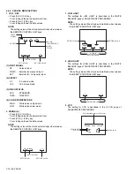
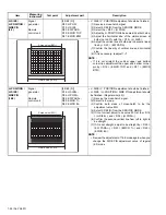
H. SIZE /
H. POSITION /
SIDE PIN
(4:3)
Signal
generator
Remote
control unit
[2.DEF (D)]
D03: H POSI
D15: H SIZE
D23: EW PARA
D19: EWCR TOP
D21: EWCR BTM
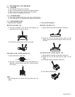
• V. SIZE / V. POSITION adjustment should be finished.
(1) Receive a cross-hatch signal.
(2) Select 2.DEF(D) from the SERVICE MODE.
(3) Select the < D03 > (H POSI).
(4) Adjust by H. POSITION to be same size at both side.
(5) Adjust the horizontal size of the visible screen at
both size to 90% with the < D15 > (H. SIZE).
(6) Adjust the vertical line at both side to become linear
line by < D23 > (EW PARA).
(7) Confirm the linearity of vertical line and horizontal
size.
(8) If it is necessary, readjust 1.~7.
NOTE :
• If it is not straight the vertical upper and bottom
corner line adjustment the upper and bottom corner
pin by < D19 > (EWCR TOP) and < D21 > (EWCR
BTM).
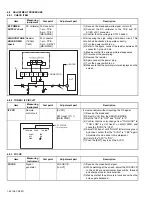
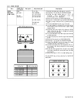
H. POSITION /
H. SIZE /
SIDE PIN
(16:9)
Signal
generator
Remote
control unit
[2.DEF (D)]
D16: H SIZE+-
D04: H POSI+-
D24: EW PARA+-
D20: EWCR T+-
D22: EWCR B+-
• V. SIZE / V. POSITION adjustment should be finished.
• H. SIZE / H. POSITION / SIDE PIN adjustment should
be finished. (Regular size(4:3)).
(1) Receive the cross-hatch signal.
(2) Select 16:9 mode.
(3) Confirm both sides of cross-hatch to be the
adjustment value 90%.
(4) Select 2.DEF(D) from the SERVICE MODE.
(5) If it not correct, adjust to be value 90% at the < D16
> (H SIZE+-) and < D04 > (H POSI+-).
(6) Confirm the second vertical line from left to right to
be straight.
(7) If it is not straight, adjust to be straight by < D24 >
(EW PARA+-), < D20 > (EWCR T+-) and < D22 >
(EWCR B+-).
NOTE :
• Review the adjustment of 16:9 mode again when you
change the SIDE PIN adjustment value of regular
(4:3) mode.
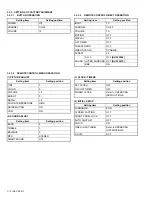
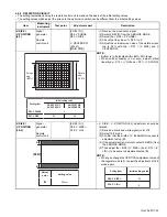
Item
Measuring
instrument
Test point
Adjustment part
Description
Picture size (100%)
Screen size (
90
%)
Picture size (100%)
Screen size (90%)


