background image

No. 51802

9

AV-32230
AV-32260

Fig.1

FRONT AV INPUT PWB

PWB
STOPPER

A

MAIN PWB

LF PWB

CRT SOCKET PWB

PICTURE TUBE

FRONT

CONTROL PWB

AV SELECTOR
PWB

CHASSIS BASE

PIP PWB (Only for AV-32260 model)

SPEAKER

FRONT CABINET

REAR COVER

K

F

(x2)

(x2)

G

(x2)

(x11)

(x2)

K

D

(x4)

E

C

J

CLAW

B

H

CLAW

B

Содержание AV 32230

Страница 1: ...C305 AV 32260 RM C306 AV 32230 AV 32230 G AV 32260 G AV 32230 H AV 32260 H AV 32230 M AV 32260 M a SPECIFICATIONS 2 a SAFETY PRECAUTIONS 3 a FEATURES 5 a MAIN DIFFERENCE LIST 6 a HOW TO IDENTIFY MODELS 6 a FUNCTIONS 7 a SPECIFIC SERVICE INSTRUCTIONS 8 a SERVICE ADJUSTMENTS 13 STANDARD CIRCUIT DIAGRAM APPENDIX 2 1 a PARTS LIST 35 CONTENTS ...

Страница 2: ...470MHz 806MHz 02 06 A 8 by 02 06 01 07 13 by 07 13 A 1 by 14 22 J W by 23 36 54MHz 804MHz W 1 W 28 by 37 64 W 29 W 84 by 65 125 A8 A4 A1 by 01 96 99 180 Channels 45 75MHz 41 25MHz 4 5MHz 3 58MHz 120V AC 60Hz 133W AV 32260 128W AV 32230 32 80cm Measured Diagonally 31kV 1 3kV at zero beam current 2 4 3 4 5 12cm Oval type 2 3W 2 Video 1 2 3 1Vp p 75Ø RCA pin jack Audio 1 2 3 500mVrms 4dBs High Impeda...

Страница 3: ...manufacturer of the complete product 8 Do not check high voltage by drawing an arc Use a high voltage meter or a high voltage probe with a VTVM Discharge the picture tube before attempting meter connection by connecting a clip lead to the ground frame and connecting the other end of the lead through a 10kØ 2W resistor to the anode button 9 When service is required observe the original lead dress E...

Страница 4: ...part Transistors diodes variable resistors etc 1 Apply extra solder to each lead 2 As shown in the figure push the part with tweezers and alter nately melt the solder at each lead Shift and remove the chip part Note After removing the part remove remaining solder from the pattern REPLACEMENT OF CHIP COMPONENT 2 How to install Chip parts Resistors capacitors etc 1 Apply solder to the pattern as ind...

Страница 5: ...2 Only for AV 32260 model Only for AV 32260 model Only for AV 32260 model SCL 1 SDA 1 SCL 0 SDA 0 AFC 2 AFC 1 Remote control unit IC301 PIP CONTROL IC001 MTS TONE SURROUND CONTROL TU001 TUNER 1 TU001 TUNER 2 IC101 1 CHIP CONTROL IC501 AVSW CONTROL 3 LINE DIGITAL COMB FILTER circuit improved picture quality Component input terminal for talking best advantage of Component Video Signal Audio Video in...

Страница 6: ...G AV 32230 H AV 32230 M MAIN PWB SAC 1535A M2 SAC 1536A M2 SAC 1537A M2 CRT SOCKET PWB SAC 3508A M2 SAC 3509A M2 SAC 3510A M2 PICTRE TUBE A80QCF240X14L A80LJF30X08 G M80JUA061X06 DEG COIL QQW0086 001 CELD066 002JA AV 32230 G AV 32230 H AV 32230 M Model Part name AV 32230 G AV 32230 H AV 32230 M RATING LABEL LC31139 001A A The difference between AV 32230 G AV 32230 H and AV 32230 M is in the PICTUR...

Страница 7: ...POWER ON TIMER VOLUME AUDIO L MONO R RM C306 1A AV 32230 POWER DISPLAY SLEEP TIMER VIDEO STATUS INPUT 1 7 4 100 3 9 6 RETURN MUTING MENU V CHIP PIP OFF EXIT 2 8 0 5 CH VOL VOL CH REC STOP PAUSE PLAY FF REW TV CATV DVD VCR VCR CHANNEL TV VCR VCR DVD POWER PREV NEXT OPEN CLOSE STILL PAUSE RM C305 HYPER SURROUND TV Model Part name AV 32260 G AV 32260 H AV 32260 M RATING LABEL LC31139 001A A The diffe...

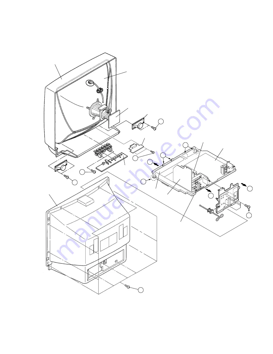
Страница 8: ...and chassis 1 Remove the 2 screws marked F and the 2 screws marked G as shown in Fig 1 2 Then remove the FRONT CONTROL PWB and FRONT AV INPUT PWB If necessary take off the wire connector s etc REMOVING THE LF PW BOARD After removing the rear cover and chassis 1 Lift the left side of the LF PWB while pressing the 2 PWB stoppers marked H in the arrow direction marked J as shown in Fig 1 2 Then remov...

Страница 9: ...RONT AV INPUT PWB PWB STOPPER A MAIN PWB LF PWB CRT SOCKET PWB PICTURE TUBE FRONT CONTROL PWB AV SELECTOR PWB CHASSIS BASE PIP PWB Only for AV 32260 model SPEAKER FRONT CABINET REAR COVER K F x2 x2 G x2 x11 x2 K D x4 E C J CLAW B H CLAW B ...

Страница 10: ...steps The CRT change table should preferably be smaller that the CRT sur face and its height be about 35cm COATING OF SILICON GREASE FOR ELECTRICAL IN SULATION ON THE CRT ANODE CAP SECTION Subsequent to replacement of the CRT and HV transformer or repair of the anode cap etc by dismounting them be sure to coat silicon grease for electrical insulation as shown in Fig 5 Wipe around the anode button ...

Страница 11: ...g items Where these differ select the setting item with the MENU UP DOWN key and adjust the setting with the MENU LEFT RIGHT keys The letters of the selected item are displayed in yellow 5 After adjusting release the MENU LEFT RIGHT key to store the setting value 6 Press the EXIT key twice to return the normal screen 5 Receive channel setting Refer to the OPERATING INSTRUCTIONS USER S GUIDE and se...

Страница 12: ...TURE CENTER BRIGHT CENTER DETAIL CENTER NOISE MUTING ON SET VIDEO STATUS ALL CENTER SOUND ADJUST BASS CENTER TREBLE CENTER BALANCE CENTER MTS STEREO CLOCK TIMERS SET CLOCK Unnecessary to set ON OFF TIMER NO INITIAL SETUP TV SPEAKER ON COMPONENT IN NO LANGUAGE ENG CLOSED CAPTION OFF AUTO TUNER SETUP TUNER MODE AIR CHANNEL SUMMARY Unnecessary to set V CHIP OFF SET LOCK CODE Unnecessary to set AV 27F...

Страница 13: ... control unit VIDEO STATUS STANDARD HYPER SURROUND OFF BASS TREBLE BALANCE CENTER TINT COLOR PICTURE CENTER BRIGHT DETAIL MEASURING INSTRUMENT 1 DC voltmeter or digital voltmeter 2 Oscilloscope 3 Signal generator Pattern generator NTSC 4 Remote control unit 5 TV audio multiplex signal generator 6 Frequency counter 7 Resistor 1MØ ADJUSTMENT ITEMS Check of B1 POWER SUPPLY RF AGC adjustment FOCUS adj...

Страница 14: ...R PWB MAIN PWB P TP E TP R TP B TP G E3 F901 125V 5A CN005 CN002 CN001 PW CN005 CN004 CN004 S1 UPPER FOCUS LOWER SCREEN MPX HV E2 E1 P CN003 CN002 CN001 J501 SS CN006 CN007 IC702 IC701 CPU DEG TU001 TU001 J601 R507 Q511 Heatsink J502 J503 CN003 TU001 FRONT FRONT POWER FRONT CONTROL PWB FRONT AV INPUT PWB VOL CH MENU 007 006 Only for AV 32260 model ...

Страница 15: ...ress the UP DOWN key of the MENU to select any of the following items The letters of the selected items are displayed in yellow AV 32230 PICTURE SOUND THEATER OTHERS LOW LIGHT HIGH LIGHT RF AFC VCO CW I2C BUS CTRL 3 Enter the any setting adjustment mode PICTURE SOUND and OTHERS mode 1 If select any of PICTURE SOUND or OTHERS items and the LEFT RIGHT key is pressed from SERVICE MENU MAIN MENU the s...

Страница 16: ... ON FINE 999 HIGH LEVEL REFERENCE LEVEL LOW LEVEL SYNC YES SELECT BY OPERATE BY EX IT EXIT BY I2C BUS ON SELECT BY OPERATE BY EX IT EXIT BY THEATER MODE 1 2 THEATER MODE 2 2 TINT 999 B CUT 999 COLOR 999 R DRIVE 999 PICTURE 999 B DRIVE 999 BRIGHT 999 DC REST 999 DETAIL 999 BLK ST 999 R CUT 999 GMM PNT 999 G CUT 999 PAGE 1 2 EX IT EXIT BY SELECT BY OPERATE BY CD MAT 99 CMP CD M 99 RY GAIN 99 CMP RY ...

Страница 17: ...ETTING VALUE will be stored memorized 3 EXIT key Returns to the previous screen 5 Releasing SERVICE MENU 1 After returning to the SERVICE MENU upon completion of the setting ad justment work press the EXIT key again The settings for LOW LIGHT and HIGH LIGHT are described in the WHITE BAL ANCE page of ADJUSTMENT 1 BRIGHT STATUS 999 99999999 SETTING ITEM INITIAL SETTING VALUE Adjust SETTING VALUE PI...

Страница 18: ...es in each item are revised independently No Setting Adjustment item Variable range Initial setting value Remark 1 BRIGHT 000 127 063 2 PICTURE 000 127 085 3 COLOR 000 127 072 4 TINT 000 127 065 5 TV DETAIL 000 063 045 6 EXT BRIGHT 025 001 7 EXT PICT 025 002 8 EXT COLOR 025 002 9 EXT TINT 025 003 10 EXT DETAIL 000 063 045 11 CMP BRIGHT 025 003 12 CMP PICT 025 006 13 CMP COLOR 000 127 089 AV 32230 ...

Страница 19: ...NT 000 003 003 53 SVM GAIN 000 003 003 54 CMP SVM GA 000 003 003 55 SVM PHASE 000 001 000 56 AUDIO SW 000 001 000 57 BUZZ 000 001 000 58 IF FREQ 000 001 000 59 RF AGC 000 063 045 60 AFT MUTE 000 001 000 61 AFT SENS 000 001 001 62 R G DRV SW 000 001 001 63 BLK SW 000 001 000 64 V S COR 000 015 012 65 V LIN 000 015 008 66 V SIZE 000 127 065 67 V AGC 000 001 000 68 V CENTER 000 063 053 69 TV AFC 000 ...

Страница 20: ...3 032 104 EX SN YC H 000 255 025 105 RF SN VC 1 000 063 000 106 RF SN VC 2 000 063 007 107 RF SN VC 3 000 063 014 108 RF SN VC 4 000 063 021 109 EX SN VC 1 000 063 000 110 EX SN VC 2 000 063 007 111 EX SN VC 3 000 063 014 112 EX SN VC 4 000 063 021 113 COR LEVEL 000 003 003 114 VNR CHK 000 255 003 115 YC SN TIME 000 255 005 116 VC SN TIME 000 255 005 117 VM DATA A 127 008 118 VM DATA B 127 004 119...

Страница 21: ...SAP VCO 000 063 003 11 IN GAIN 000 001 000 12 FIL OFFSET 010 000 13 BBE BASS 010 001 14 BBE TRE 010 002 SOUND MODE Setting Adjustment item Variable range Initial setting value Remark TINT 20 06 COLOR 20 03 PICTURE 50 15 BRIGHT 20 00 DETAIL 20 03 R CUT 20 00 G CUT 20 00 B CUT 20 00 R DRIVE 99 07 B DRIVE 99 25 DC REST 00 03 01 BLK ST 00 03 00 GMM PNT 00 03 01 CD MATRIX 00 03 01 RY GAIN 00 01 01 GY P...

Страница 22: ...0 015 003 6 P G CUT 000 015 000 7 P B CUT 000 015 002 8 P R DR 000 255 052 9 P G DR 000 255 055 10 P B DR 000 255 060 11 LEFT POS 000 255 020 12 RIGHT POS 000 255 017 13 UPPER POS 000 127 012 14 LOWER POS 000 127 011 15 PICT LOCK 000 001 001 16 SELDEL 000 015 000 17 AGCFIX 000 001 001 18 AGCADST 000 001 000 19 AGC 000 015 007 20 VSPDEL 000 031 000 21 VSPISQ 000 001 001 22 YCOR 000 001 001 23 XFREQ...

Страница 23: ...e Initial setting value Remark RF AFC1 ON OFF ON FINE 77 77 RF AFC1 MODE Only for AV 32260 model DO NOT ADJUST Setting Adjustment item Variable range Initial setting value Remark RF AFC2 ON OFF ON FINE 77 77 RF AFC2 MODE Only for AV 32260 model DO NOT ADJUST Setting Adjustment item Variable range Initial setting value Remark I2C BUS ON OFF FIXED ON I2C BUS CTRL MODE DO NOT ADJUST Setting Adjustmen...

Страница 24: ...he MUTE key and get color out No 59 RF AGC Item Measuring instrument Test point Adjustment part Description ADJUSTMENT OF RF AGC FOCUS adjustment Signal generator Notes Proceed to the following this adjustment after having completed the adjustments of B1 POWER SUPPLY SUB BRIGHT and PICTURE Set VIDEO STATUS to STANDARD The final adjustment of CONVERGENCE must be done after the FOCUS adjustment CONV...

Страница 25: ... is the cancel key for the WHITE BALANCE Notes Proceed to the following this adjustment after having completed the adjustment of LOW LIGHT WHITE BALANCE Set VIDEO STATUS to STANDARD 1 Receive a black and white signal Color off 2 Select the HIGH LIGHT MODE from the SERVICE MENU 3 Set the initial setting value of R DRIVE and B DRIVE is 060 with the 4 6 7 and 9 keys of the remote control unit 4 Adjus...

Страница 26: ... WHITE BALANCE Set VIDEO STATUS to STANDARD 1 Receive a broadcast 2 Select the No 1 BRIGHT of the PICTURE MODE 3 Set the initial setting value of the No 1 BRIGHT with the LEFT RIGHT key of the remote control unit 4 If the brightness is not best with the initial setting value make fine adjustment of the No 1 BRIGHT until you get the optimum bright ness SUB CONTRAST Adjustment Notes Proceed to the f...

Страница 27: ...TER TRAPEZIUM V SIZE and V LINEARITY 1 Receive a crosshatch signal 2 Select the No 73 H SIZE of the PICTURE MODE 3 Set the initial setting value of the No 73 H SIZE with the LEFT RIGHT key of the remote control unit 4 Adjust the No 73 H SIZE until the horizontal screen size is 92 5 Adjust the No 72 H POSI until the screen will be horizontally centered No 73 H SIZE No 72 H POSI V SIZE and V LINEARI...

Страница 28: ...t the end of vertical 2nd lines from left and right to be straight at the No 82 TOP PIN and the No 84 BTM PIN of the PICTURE MODE PIP DISPLAY POSITION Adjustment AV 32260 Notes Proceed to the following this adjustment after having completed the adjustments of V CENTER TRAPEZIUM V SIZE V LINEARITY H SIZE H POSITION SIDE PIN and CORNER PIN for the main pic ture Set VIDEO STATUS to STANDARD 1 Receive...

Страница 29: ... illustration to the voltage shown in the table 1 SUB TINT adjustment Notes Proceed to the following this adjustment after having completed the adjustment of CONTRAST Set VIDEO STATUS to STANDARD Method of adjustment without measuring instrument 1 Receive a broadcast 2 Select the No 4 TINT of the PICTURE MODE 3 Set the initial setting value of the No 4 TINT with the LEFT RIGHT key of the remote co...

Страница 30: ...pin 2 of MPX con nector and enlarge the voltage axis 4 Select the No 7 LOW SEP of the SOUND MODE 5 Set the initial setting value of the No 7 LOW SEP with the LEFT RIGHT key of the remote control unit 6 Adjust the No 7 LOW SEP so that the 300Hz signal level will be come minimum 7 Change the signal to 3kHz and connect an oscilloscope to pin 1 of MPX connector 8 Adjust the No 8 HI SEP so that the 3kH...

Страница 31: ...lug and position them horizontally Fig 2 7 Adjust the gap between two lugs so that the GREEN RASTER will come into the center of the screen Fig 3 8 Move the deflection yoke forward and fix the position of the deflec tion yoke so that the whole screen will become green 9 Insert the wedge to the top side of the deflection yoke so that it will not move 10 Input a crosshatch signal 11 Verify that the ...

Страница 32: ...nd make best convergence DYNAMIC CONVERGENCE ADJUSTMENT 1 Move the deflection yoke up and down and overlap the lines in the periphery Fig 5 2 Move the deflection yoke left to right and overlap the lines in the periphery Fig 6 3 Repeat 1 and 2 above and make best convergence After adjustment fix the wedge at the original position Fasten the retainer screw of the deflection yoke Fix the 6 magnets wi...

Страница 33: ...rn the POWER SW ON 2 As shown in Fig 1 set the resistor between S1 connector 2 3 3 Make sure that the screen picture disappears 4 Temporarily unplug the power cord 5 Remove the resistor between S1 connector 2 3 6 Again plug the power cord make sure that the normal picture is displayed on the screen Fig 1 2 3 S1 CONNECTOR HEATER RESISTOR 25 9 kΩ 129 Ω 1 4 W POWER ON OFF RY951 R952 D535 R532 R951 Q9...

Страница 34: ... supplied In the event a malfunction is detected the power is cut off immedi ately At this time the ON TIMER LED flashes to inform of the malfunc tion ON TIMER LED indication The ON TIMER LED flashes at 0 5 seconds intervals POWER Supplied After about 5 seconds Start of detection Malfunction is detected POWER OFF Flashing ON TIMER LED Over current protector Operation of B1 protector circuit The mi...

Страница 35: ...ess California 90630 714 229 8011 Southwest 10700 Hammerly Suite 105 Houston Texas 77043 713 935 9331 Hawaii 2969 Mapunapuna Place Honolulu Hawaii 96819 808 833 5828 Southeast 1500 Lakes Parkway Lawrenceville Georgia 30243 770 339 2582 JVC CANADA INC Head office 21 Finchdene Square Scarborough Ontario M1X 1A7 416 293 1311 Vancouver 13040 Worster Court Richmond B C V6V 2B3 604 270 1311 DIVISION OF ...

Отзывы: