background image

1-4 (No.YA261)

1.2

SAFETY PRECAUTIONS [FOR UK]

(1) The design of this product contains special hardware and many circuits and components specially for safety purposes. For

continued protection, no changes should be made to the original design unless authorized in writing by the manufacturer.
Replacement parts must be identical to those used in the original circuits. Service should be performed by qualified personnel
only.

(2) Alterations of the design or circuitry of the product should not be made. Any design alterations or additions will void the

manufacturer's warranty and will further relieve the manufacturer of responsibility for personal injury or property damage
resulting therefrom.

(3) Many electrical and mechanical parts in the product have special safety-related characteristics. These characteristics are often

not evident from visual inspection nor can the protection afforded by them necessary be obtained by using replacement
components rated for higher voltage, wattage, etc. Replacement parts which have these special safety characteristics are
identified in the Parts List of Service Manual. Electrical components having such features are identified by shading on the
schematics and by (   ) on the Parts List in the Service Manual. The use of a substitute replacement which does not have the
same safety characteristics as the recommended replacement part shown in the Parts List of Service Manual may cause shock,
fire, or other hazards.

(4) The leads in the products are routed and dressed with ties, clamps, tubing’s, barriers and the like to be separated from live parts,

high temperature parts, moving parts and / or sharp edges for the prevention of electric shock and fire hazard. When service is
required, the original lead routing and dress should be observed, and it should be confirmed that they have been returned to
normal, after re-assembling.

WARNING

(1) The equipment has been designed and manufactured to meet international safety standards.
(2) It is the legal responsibility of the repairer to ensure that these safety standards are maintained.
(3) Repairs must be made in accordance with the relevant safety standards.
(4) It is essential that safety critical components are replaced by approved parts.
(5) If mains voltage selector is provided, check setting for local voltage.

Содержание AV-28T5BK

Страница 1: ...y was changed based on AV 28T5BK AV 28T5BR AV 28T5SK AV 28T5SR AV 28T5SP Therefore this service manual describes only the items which differ from those of the AV 28T5BK AV 28T5BR AV 28T5SK AV 28T5SR and AV 28T5SP service manual For details other than those described in this manual please refer to the AV 28T5BK AV 28T5BR AV 28T5SK AV 28T5SR and AV 28T5SP service manual No YA261 2005 3 PE is added t...

Страница 2: ... SJW 3012A U2 LCA90245 05B CRT SOCKET PWB 41 SJW 8011A U2 LCA90300 02A FRONT CONTROL PWB 42 SJW 2012A S2 LCA10364 09C POWER DEF PWB 43 SJW0J011A U2 LCA90248 02C AV JACK PWB 45 SJW 8111A U2 LCA90301 02B SIDE CONTROL PWB Ref No Part No PART NAME DESCRIPTION AV 28T5BR AV 28T5BR P 26 LC11364 078A U LC11364 088A U RATING LABEL 40 SJW 3012A U2 LCA90245 05B CRT SOCKET PWB 41 SJW 8011A U2 LCA90300 02A FRO...

Страница 3: ...TION AV 28T5BK AV 28T5BR AV 28T5SK AV 28T5SR AV 28T5SP AV 28T5BK P AV 28T5BR P AV 28T5SK P AV 28T5SR P AV 28T5SP P SJW 2012A U2 LCA10364 09C Q571 DTC124ESA T DIGI TRANSISTOR Delete Q572 KTC3199 YG T TRANSISTOR Delete Q573 RDN050N20 POWER MOS FET Delete Q574 RDN050N20 POWER MOS FET Delete D909 AU01Z T2 FR DIODE Addition D910 AU01Z T2 FR DIODE Addition D955 FSF05A20 FMX G12S SI DIODE C524 QFM72DK 10...

Страница 4: ...Ω 1 4W J CN0HV CHC802T 05N J CHC802T 05N T LV CONNECTOR K902 QQR0621 002Z FERRITE BEADS Delete PC571 PC123Y22FZ PHOTO COUPLER Delete TH901 CEKP002 003 QAD0121 9R0 P THERMISTOR 9Ω Ref No Part No PART NAME DESCRIPTION AV 28T5BK AV 28T5BR AV 28T5SK AV 28T5SR AV 28T5SP AV 28T5BK P AV 28T5BR P AV 28T5SK P AV 28T5SR P AV 28T5SP P SJW 2012A U2 LCA10364 09C Ref No Part No PART NAME DESCRIPTION AV 28T5BK A...

Страница 5: ...AV 28T5SK AV 28T5SR AV 28T5SP No YA261 about this section SECTION 3 DISASSEMBLY Please refer to AV 28T5BK AV 28T5BR AV 28T5SK AV 28T5SR AV 28T5SP No YA261 about this section SECTION 4 ADJUSTMENT Please refer to AV 28T5BK AV 28T5BR AV 28T5SK AV 28T5SR AV 28T5SP No YA261 about this section SECTION 5 TROUBLESHOOTING Please refer to AV 28T5BK AV 28T5BR AV 28T5SK AV 28T5SR AV 28T5SP No YA261 about this...

Страница 6: ... No YA261B AV MULTIMEDIA COMPANY DISPLAY CATEGORY 12 3 chome Moriya cho Kanagawa ku Yokohama city Kanagawa prefecture 221 8528 Japan Victor Company of Japan Limited VPT Printed in Japan ...

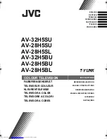
Страница 7: ...3 COLOUR TELEVISION YA261 2005 3 AV 28T5BK AV 28T5BR AV 28T5SK AV 28T5SP AV 28T5SR TABLE OF CONTENTS 1 PRECAUTION 1 3 2 SPECIFIC SERVICE INSTRUCTIONS 1 5 3 DISASSEMBLY 1 7 4 ADJUSTMENT 1 13 5 TROUBLE SHOOTING 1 27 BASIC CHASSIS JW2 1 4 7 2 5 8 0 3 6 9 P AV TV OK MENU P TV F T L ...

Страница 8: ...ency PAL 4 43MHz SECAM 4 40625MHz 4 25MHz NTSC 3 58MHz 4 43MHz Teletext System FLOF Fastext WST Standard system TOP German system FLOF Fastext WST Standard system Power Input AC220V AC240V 50Hz Power Consumption 110W Standby 2 7W Picture Tube Visible size 66cm measured diagonally H 58 3cm V 33 0cm High Voltage 31 0kV 1kV 1 5kV at zero beam current Speaker 13cm 6 5cm oval type 2 Audio Power Output ...

Страница 9: ...replacements or alternatives approved by the manufacturer of the complete product 7 Do not check high voltage by drawing an arc Use a high voltage meter or a high voltage probe with a VTVM Discharge the picture tube before attempting meter connection by connecting a clip lead to the ground frame and connecting the other end of the lead through a 10kΩ 2W resistor to the anode button 8 When service ...

Страница 10: ...aracteristics are identified in the Parts List of Service Manual Electrical components having such features are identified by shading on the schematics and by on the Parts List in the Service Manual The use of a substitute replacement which does not have the same safety characteristics as the recommended replacement part shown in the Parts List of Service Manual may cause shock fire or other hazar...

Страница 11: ...ut 500mV rms Nominal Low impedance Used TV OUT Used LINE OUT Not used 2 AUDIO R input 500mV rms Nominal High impedance Used R1 Used R2 Used R3 3 AUDIO L output 500mV rms Nominal Low impedance Used TV OUT Used LINE OUT Not used 4 AUDIO GND Used Used Used 5 GND B Used Used Used 6 AUDIO L input 500mV rms Nominal High impedance Used L1 Used L2 Used L3 7 B input 700mV B W 75Ω Used Used Not used 8 FUNCT...

Страница 12: ...fIn Avl RefOut O L Other SW L H 97 REMOCON I Remote control 34 AudoIn5L I Not used 98 P10 Int1 I AV_LINK control 35 AudioIn5R I Not used 99 P11 TO O AV_LINK control 36 AudOutSL O Audio Left 100 V1 8C2 I 1 8V 37 AudOutSR O Audio Right 101 VssC2 GND 38 DecsDem Not used 102 P04 I2SWs Not used 39 QssO AmO AudeEm Not used 103 P03 I2SClk Not used 40 Gnd2 GND 104 P02 I2SDo2 Not used 41 PllIf Not used 105...

Страница 13: ... TERMINAL BOARD Remove the REAR COVER 1 Remove the 2 screws D 2 Remove the 2 claws under the CHASSIS then remove the AV TERMINAL BOARD 3 1 6 REMOVING THE SPEAKER Remove the REAR COVER Remove the CHASSIS BASE 1 Remove the 4 screws E then remove the SPEAKER 2 Follow the same steps when removing the other hand MAIN SPEAKER 3 1 7 CHECKING THE PW BOARD To check the back side of the PW Board 1 Pull out ...

Страница 14: ...ASE FRONT CONTROL PWB MAIN PWB CHASSIS BASE AV JACK PWB POWER CORD POWER DEF PWB AV TERMINAL BOARD Claw Claw Claw Claw REAR COVER SIDE CONTROL BASE SIDE CONTROL JACK ASSY SIDE CONTROL PWB CRT SOCKET PWB SPEAKER SPEAKER A B C E D E ...

Страница 15: ...here these differ select the addres with the FUNCTION key and adjust it with the FUNCTION keys The letter of the selected item is displayed in yellow 5 Setup will become effective if the main power is shut off 5 Receiving channel setting Refer to the OPERATING INSTRUCTIONS and set the receive channels Channels Preset as described 6 User settings Check the user setting items according to the given ...

Страница 16: ...et CH EXT AUTO 4 3 AUTO ASPECT PANORAMIC Setting item Setting position STEREO I II Stereo sound BASS 2 TREBLE 2 BALANCE Centre HYPER SOUND OFF Setting item Setting position SLEEP TIMER OFF BLUE BACK ON CHILD LOCK OFF Setting item Setting position AUTO PROGRAM TV channel automatically set EDIT MANUAL PRESET CH only The others BLANK LANGUAGE ENGLISH DECODER EXT 2 OFF EXT SETTING ID BLANK S IN BLANK ...

Страница 17: ...1 BOW 12 V S CR 13 V LIN 2 V C 1 SCREEN 2 CUTOFF R G 3 WDR R G B 4 BRIGHT 5 CONT 6 COLOUR 7 HUE 8 BLACK OFFSET B Y 9 SHARP 10 Y DELAY 11 TINT DVD 12 RGB BLK 5 VSM PRESET BRIGHT SOFT STANDARD 1 BRIGHT 2 CONT 3 COLOUR 4 SHARP 5 HUE COOL WARM NORMAL 1 R DRIVE 2 G DRIVE 3 B DRIVE 3 AUDIO Do not adjust 1 DCX0 ADJ 2 NICAM LOWER ERRLIM 3 NICAM UPPER ERRLIM 4 A2 ID THR 6 VPS Do not adjust VPS PDC WSS SN 7...

Страница 18: ...he tweezers and remove the chip part Transistors diodes variable resistors etc 1 Apply extra solder to each lead 2 As shown in the figure push the part with tweezers and alternately melt the solder at each lead Shift and remove the chip part NOTE After removing the part remove remaining solder from the pattern 2 How to install Chip parts Resistors capacitors etc 1 Apply solder to the pattern as in...

Страница 19: ...wn in the adjustment items of this service adjustment 4 2 PRESET SETTING BEFORE ADJUSTMENT Unless otherwise specified in the adjustment items preset the following functions with the REMOTE CONTROL UNIT 4 3 MEASURING INSTRUMENT AND FIXTURES 1 DC voltmeter or digital voltmeter 2 Oscilloscope 3 Signal generator Pattern generator PAL SECAM NTSC 4 Remote control unit 4 4 ADJUSTMENT ITEMS CHECK ITEM B1 ...

Страница 20: ...EN CN003 CN009 CN001 CN3008 CN3009 CN004 CN008 MAIN PWB AV JACK PWB POWER DEF PWB PW DEG TUNER FRONT FRONT FRONT TOP CRT SOCKET PWB SOLDER SIDE FRONT CONTROL PWB SIDE CONTROL PWB SPEAKER POWER CORD 1 TP 91 B1 2 TP E 3 X RAY1 4 X RAY2 5 TP E DEF YOKE DEG COIL TP 47R TP 47G TP E TP 47B 1 5 ...

Страница 21: ...rize the setting value Before storing the setting values in memory do not press the CH TV POWER ON OFF key if you do the values will not be stored in memory 5 INFORMATION key Return to the SERVICE MODE main manu screen 3 AUDIO 6 VPS and 7 SHIPPING OFF It is not requirement to adjustment 4 6 2 4 MEMORIZE THE ADJUSTMENT DATA When adjustment is completed press the MENU key to memorize the adjustment ...

Страница 22: ...ID THR AUDIO 3 AUDIO 1 DCX0 ADJ NOT NICAM 1 VCO 1 IF 2 DELAY POINT BRIGHT STANDARD SOFT 5 VSM PRESET VSM PRESET BRIGHT 1 BRIGHT 1 BRIGHT 2 CONT 3 COLOUR 4 SHARP 5 HUE 1 R DRIVE 2 G DRIVE 3 B DRIVE Do not adjust Do not adjust PICTURE MODE COOL NORMAL WARM COLOUR TEMP 1 SCREEN 2 CUTOFF R G 3 WDR R G B 4 BRIGHT 5 CONT 6 COLOUR 7 HUE 12 RGB BLK 8 BLACK OFFSET B Y 9 SHARP 10 Y DELAY 11 TINT DVD VCO CW ...

Страница 23: ...EN 63 63 0 0 0 0 0 3 WDR RED 63 63 0 0 0 0 5 GREEN 63 63 0 0 0 0 0 BLUE 63 63 0 0 0 0 5 4 BRIGHT 63 63 0 0 0 0 0 5 CONT 63 63 10 10 10 10 0 6 COLOUR 63 63 0 0 0 0 3 7 HUE 63 63 0 0 8 BLACK OFFSET B Y 0 3 3 Setting item Variable range Setting value PAL SECAM NTSC NTSC4 43 RGB RF VIDEO RF VIDEO RF VIDEO RF VIDEO 9 SHARP 63 63 5 5 5 5 5 5 5 5 5 Setting item Variable range Setting value PAL SECAM NTSC...

Страница 24: ... 20 1 1 0 0 0 12 0 8 0 4 0 6 TRAPEZ 32 31 0 1 0 0 3 0 0 0 0 0 0 0 7 EW PIN 32 31 14 0 0 0 0 0 0 0 2 0 0 0 8 COR UP 32 31 0 0 0 0 0 0 0 0 0 0 0 0 9 COR LO 32 31 0 0 3 0 8 0 0 0 0 0 0 0 10 ANGLE 32 31 0 1 0 0 0 0 0 0 0 0 0 0 11 BOW 32 31 0 0 0 0 0 0 0 0 0 0 0 0 12 V S CR 32 31 14 3 10 0 8 0 0 0 0 0 0 0 13 V LIN 32 31 5 0 0 0 16 0 0 0 0 0 0 0 Item Variable range Setting value PICTURE MODE COLOUR TEMP...

Страница 25: ...ect a HV voltmeter to CRT ANODE and chassis GND Ground side is connected previously 6 Make sure that the voltage is DC 31 0kV 1kV 1 5kV 7 Press the FUNCTION key to return to SERVICE MODE NOTE Remove the probe before removing the earth clip IF VCO Remote control unit 1 IF 1 VCO Under normal conditions no adjustment is required It must not adjust without broadcast signal 1 Receive the any broadcast ...

Страница 26: ...ake A B 6 Check the adjustment value above in other zoom mode If it is a wrong adjustment readjust in FULL mode and adjust by 1 V SHIFT 7 Press the MENU key to memorize the set value V SIZE Signal generator Remote control unit 4 DEF 3 V SIZE 1 Receive the cross hatch signal 2 Set the ZOOM mode to FULL 3 Select 4 DEF from the SERVICE MODE 4 Set the initial setting value of 3 V SIZE 5 Adjust to make...

Страница 27: ...lect 4 DEF from the SERVICE MODE 4 Set the initial setting value of 7 EW PIN 5 Adjust to make the vertical lines at the right and left edges of the screen straight Also make sure that the 3rd vertical lines are straight 6 Press the MENU key to memorize the set value TRAPEZIUM Signal generator Remote control unit 4 DEF 6 TRAPEZ 1 Receive the cross hatch signal 2 Set the ZOOM mode to FULL 3 Select 4...

Страница 28: ...grammical distortion of images on the screen 1 Receive the cross hatch signal 2 Set the ZOOM mode to FULL 3 Select 4 DEF from the SERVICE MODE 4 Set the initial setting value of 10 ANGLE 5 Adjust to bring the vertical lines straight 6 Press the MENU key to memorize the set value BOW Signal generator Remote control unit 4 DEF 11 BOW In case where there is a bow shaped distortion of images on the sc...

Страница 29: ...e black portion in the screen becomes black 8 Select 3 WDR 9 Each select R B and adjust the screen until the white portion in the screen becomes white NOTE Do not adjust 3 WDR G 10 Press the MENU key to memorize the set value 11 Change the contrast and brightness from low light to high light and check that the tracking of the white balance is good SUB BRIGHT Remote control unit 2 V C 4 BRIGHT 1 Re...

Страница 30: ...ol unit TP 47B TP E CRT SOCKET PWB 2 V C 6 COLOUR Method of adjustment using measuring instrument PAL COLOUR 1 Receive the PAL full field colour bar signal 75 white 2 Set the ZOOM mode to FULL 3 Set the PICTURE mode to STANDARD 4 Select 2 V C from the SERVICE MODE 5 Set the initial setting value of 6 COLOUR 6 Connect the oscilloscope between TP 47B and TP E 7 Adjust 6 COLOUR and bring the value of...

Страница 31: ... at the respective values Signal generator Oscilloscope Remote control unit TP 47B TP E CRT SOCKET PWB 2 V C 7 HUE Method of adjustment using measuring instrument NTSC 3 58 TINT 1 Input the NTSC 3 58MHz signal full field colour bar with 75 white from the EXT terminal 2 Set the ZOOM mode to FULL 3 Set the PICTURE mode to STANDARD 4 Select 2 V C from the SERVICE MODE 5 Set the initial setting value ...

Страница 32: ... 9 REMOTE CONTROL UNIT KEY B Y B Y Colour mode B W mode R Y R Y Item Measuring instrument Test point Adjustment part Description VSM PRESET Remote control unit 5 VSM PRESET 1 BRIGHT 2 CONT 3 COLOUR 4 SHARP 5 HUE 1 R DRIVE 2 G DRIVE 3 B DRIVE 1 Select 5 VSM PRESET from the SERVICE MODE 2 Set the PICTURE MODE to BRIGHT 3 Select 1 BRIGHT 4 Set the initial setting value of PICTURE MODE as shown in the...

Страница 33: ... No YA261 1 27 SECTION 5 TROUBLE SHOOTING This service manual does not describe TROUBLE SHOOTING ...

Страница 34: ... No YA261 AV MULTIMEDIA COMPANY VIDEO DISPLAY CATEGORY 12 3 chome Moriya cho kanagawa ku Yokohama kanagawa prefecture 221 8528 Japan Victor Company of Japan Limited VPT Printed in Japan ...

Страница 35: ...ompany of Japan Limited No YA261 2005 3 COLOUR TELEVISION YA261 2005 3 AV 28T5SP AV 28T5SK AV 28T5SR AV 28T5BR AV 28T5BK BASIC CHASSIS JW2 1 4 7 2 5 8 0 3 6 9 P AV TV OK MENU P TV F T L SCHEMATIC DIAGRAMS CD ROM No SML200503 ...

Страница 36: ...ype MM Metalized mylar capacitor PP Polypropylene capacitor MPP Metalized polypropylene capacitor MF Metalized film capacitor TF Thin film capacitor BP Bipolar electrolytic capacitor TAN Tantalum capacitor 3 Coils No unit Others µH As specified No indication Ceramic capacitor 2 Capacitors Capacitance value 1 or higher pF less than 1 µF Withstand voltage No indication DC50 V Others DC withstand vol...

Страница 37: ... 2 25 FRONT BOARD PWB PATTERN 2 26 SIDE BOARD PWB PATTERN 2 26 VOLTAGE CHARTS 2 27 WAVE FORMS 2 28 USING P W BOARD IC BOTTOM VIEW FRONT VIEW TOP VIEW 1 N N 1 OUT E IN IN OUT E 1 N TOP VIEW 1 N 1 N CHIP IC TRANSISTOR BOTTOM VIEW FRONT VIEW TOP VIEW CHIP TR E C B E C B C B E B G E S C D E C B E C B P W B ASS Y name AV 28T5SP MAIN P W BOARD CRT SOCKET P W BOARD AV JACK P W BOARD POWER DEF P W BOARD F...

Страница 38: ... OUT VM AMP R G B R G B TU101 TUNER V4 L4 L4 R4 L4 R4 R4 L3 R3 L3 R3 Y3 C3 Y3 C3 V3 V3 VM EW VM VD IC602 AUDIO OUT IC603 TONE VOLUME CONTROL IC702 MEMORY SPEAKER R SPEAKER L KEY REMOCON SF101 SAW FILTER SF102 SAW FILTER VIDEO IF AGC AFT VIDEO AMP QSS SOUND IF AGC AM DEMODULATOR H V SYNC SEP H OSC DRIVE V DRIVE VELOCITY SCAN MODULATION RGB CONTROL OSD TEXT INSERT RGB MATRIX VIDEO SW VIDEO FILTER RG...

Страница 39: ... GndA V1 8ADC VssADC V3 3A2 V1 8A TDA12020H N1D01 A0 A1 A2 VSS VCC WP SCL SDA M24C16 WBN6 AT24C08A10PI2 7 6 3 50 16 16 16 50 QFVF1HJ 104Z SJW 1913A 50 50 16 16 2SA562TM Y T 1 2W 1 2W 16 SJW 1913A 16 RESET SJW 1912A RESET 16 RB161L 40 X SJW 1012A SJW 1914A SJW 1012A SJW 1911A SJW 1912A 50 CH D G S D G S AMP 2SC5397 CD T IF NC BT NC BP MB SDA SCL ADRS NC AGC TUNER QAX0531 001 QAU0373 001 002 QAU0344...

Страница 40: ... BUFFER BUFFER F F F ROTATION QGB1506L1 16 F SJW 1011A QGA2501 C5 03Z SJW 1012A LA6515 MUTING MUTING UN2226 X MUTING UN2226 X SJW 1911A SJW 1912A SJW 1913A CH CH SJW 1914A SW QJK002 034423 E 16 NCB11EK 105X CXA2089Q X QQR0621 002Z QQR0621 002Z AN78L09 T 16 16 16 QGA2501C5 06Z 50 CH N 16 CH ZD12 100 01 01 100 01 150 OPEN 75 100 100 10 680 1k 68 100 180 100 100 100 ZD12 100 100 100 100 100 OPEN OPEN...

Страница 41: ...2A AN7585 SJW 1012A LC32265 003A SJW 1012A CH QETM1VM 228 QGA2501C5 03Z SJW 1911A SJW 1912A QETM1EM 338 SJW 1914A AN5277 SJW 1914A SJW 1914A SJW 1914A UN2213 X SJW 1011A SJW 1913A SJW 1011A SJW 1011A SJW 1912A SJW 1911A SJW 1911A QGB1505 J1 35 SJW 1011A SJW 1011A SJW 1911A SJW 1912A SJW 1912A SJW 1012A BD3869 AF X 1 2W QRE121J 562Y LC32265 001A LC32265 002A AN7585 1 2W R1 2 CH SJW 1913A SJW 1913A ...

Страница 42: ...A2501C1 03Z R1 2 500V R1 2 FR105GT T3 16 2SC4793 QCB32HK 472Z FR105GT T3 160 QQL244J 391Z QCB32HK 472Z R1 2 16 10 CH QRZ0107 152Z QETM2EM 106 QRZ0107 152Z TDA6107AJF N1 QRZ0107 152Z 250 QETM2EM 336 QRE121J 105Y CH QGZ8005C3 01 QQR0621 002Z QJK002 063231 E QJK002 062611 E R1 2 BK GK RK QNZ0536 001 W76QEN693X001 QGZ0017C1 01Z SJW 3012A QNZ0536 001 QRZ0107 474Z 50 3011A SJW 16 QCZ0131 222 VM1 QFK62EK...

Страница 43: ...LC0122 R0101 R0103 C0101 C0104 R0123 R0122 J0001 C0106 R0106 C0105 C0107 C0108 R0108 C0109 C0110 2 2 QNZ0465 001 QGB1505K1 35 50 50 50 NQR0389 003X NQR0389 003X NQR0389 003X QNZ0463 001 1 2 QNZ0465 001 CH CH 10 10 ZD5 6 ZD5 6 10 OPEN ZD5 6 ZD5 6 ZD5 6 75 75 75 75 75 ZD5 6 ZD5 6 ZD5 6 0047 OPEN OPEN 0047 75 75 75 ZD5 6 OPEN OPEN 0 0 OPEN 75 75 0047 0047 0 0 220p 75 0047 0047 220p 75 0047 0047 GND A...

Страница 44: ... PC123Y22FZ 200V MPP QQLZ036 821 SJW 2014A CH SJW 2013A QRL039J 222 KTC3199 YG T 25 QRL039J 222 CH 1 2W DTC124ESA T D M SW D G S RDN050N20 QFZ0197 154 QFZ0197 124 ICP N70 T 002Z QQR0621 1W_OMF QRG01GJ 820 FMX G12S 001A LC33021 SW 10 1 QQLZ026 460 QRT039J 1R2 1 QRT039J 1R2 QRZ9021 1R2 QETM1VM 228 QRF104K 3R9 H OUT 2SC5902 RL QRL039J 332 QRL039J 332 QRL039J 103 QRT039J 1R5 QRT039J 1R5 QRZ9021 4R7 1 ...

Страница 45: ...002 001Z QMF51D2 3R15 J1 STD BY BRIGHT LH22440 T16 WJK0200 008A E SW UN2212 X RPM7238 H5 16 QSW0824 001 CEMG002 001Z 16 QGAB801F1 02 SW UN2212 X 1 2W QRE121J 470Y or AC275V QFZ9072 474 QFZ9075 474 QQR1095 001 QGA2501C5 04Z POW_LED REMOCON GND STB_VCC T3 15AH 560 1 OPEN OPEN OPEN OPEN 100 1k 33k 3 3k OPEN 47 OPEN OPEN 47 3 3V GND POW_LED FRONT BOARD PWB ASS Y SJW 8011A U2 POWER DEF PWB MAIN PWB 2 3...

Страница 46: ...132 K8131 C8103 QGA2501F1 05 QGA2501F1 06 QGA2501F1 03 QNN0591 001 R4IN 16 V4 QMS3001 C01 QSW0619 003Z QSW0619 003Z QSW0619 003Z QQL244K 5R6Z QQL244K 5R6Z 1 2W 1 2W NQR0389 003X QQL244K 270Z QQL244K 270Z NQR0389 003X 820 01 01 OPEN OPEN 1 5k V_GND 0047 0047 OPEN OPEN OPEN OPEN V_GND 001 75 1 A_GND V_GND 1k 1k GND 5 6 5 6 270 270 27 27 001 HP_DET KEY A_GND SIDE BOARD PWB ASS Y SJW 8111A U2 MAIN PWB...

Страница 47: ...635 R636 R637 R638 R639 R640 R641 R642 R643 W816 W630 R646 R647 R648 49 R6 R650 R652 R653 R654 R655 R656 W817 W631 W360 R660 R661 R662 R663 R664 R701 R704 R705 R789 R707 R709 R710 R711 R712 R713 R714 R715 R717 R719 R720 R721 R722 R723 R724 R725 R726 R727 R728 R729 R730 R733 R734 R735 R736 R737 R738 R739 R740 R741 R742 R743 R744 R745 R746 R747 R749 R750 R751 R752 R753 R754 R755 R756 R757 D619 D620 ...

Страница 48: ...402 Q461 R545 R546 Q501 Q521 Q591 Q592 Q593 Q931 Q932 Q934 R401 R402 R403 R404 R413 R414 R415 R416 R417 R461 R462 W624 W625 Y401 C913 R467 R492 R493 R494 R495 R496 R497 R501 R502 R503 R504 R505 R521 R522 R523 R524 R525 R526 R541 R542 R543 R551 R552 R553 R554 R555 R561 R562 R563 R591 R592 R593 R594 R595 R596 R597 R902 R903 R904 R905 R907 R908 R909 R911 R912 R913 R914 R915 R916 R917 R918 R932 R933 R...

Страница 49: ...W3207 W3409 W3609 W3208 W3209 W3410 K3305 E2 HS3309 HS3310 HS3101 C8851 C8852 C8901 PW B W D8801 D8851 F8901 LF8901 Q8801 Q8802 R8801 R8802 R8803 R8804 R8851 S8901 VA8901 Y8905 Y8906 Y8907 Y8908 W8201 W8202 W8203 W8204 FC8901 FC8902 R8852 IC8851 C8101 C8102 C8103 C8104 C8105 C8106 C8131 C8132 C8133 F K S J8111 J8131 J8132 K8111 K8131 L8111 L8112 L8131 L8132 R8111 R8112 R8113 R8114 R8131 R8132 R813...

Страница 50: ...22 4 5 23 4 8 24 4 5 25 0 26 2 8 27 2 7 28 0 5 29 4 4 30 4 5 31 3 6 32 4 5 33 3 6 34 9 35 0 36 4 9 37 4 5 38 4 5 39 4 5 40 4 4 41 4 5 42 3 7 43 4 1 44 0 45 4 3 46 4 5 47 3 9 48 4 5 IC 902 1 11 8 2 0 3 9 1 Q 201 E 2 8 C 4 B 0 Q 202 E 1 2 C 2 B 0 Q 207 E 0 C 0 B 1 7 Q 210 E 0 C 1 6 B 0 Q 211 E 0 C 0 B 1 6 Q 212 E 0 C 1 7 B 0 Q 213 E 0 C 0 B 1 7 Q 214 E 0 C 0 B 1 6 Q 215 E 3 5 C 0 B 2 8 Q 217 E 2 9 C...

Страница 51: ...IC201 23 1 5 Vp p H IC201 33 3 Vp p H IC201 40 2 2 Vp p H IC201 43 2 2 Vp p H IC3101 1 1 4Vp p H IC3101 2 1 2 Vp p H IC3101 3 1 5 Vp p H IC401 1 1 2 Vp p V IC401 7 1 5 Vp p V IC401 5 45 Vp p V Q501 D 150 Vp p H Q521 B 2 2 Vp p H Q521 C 1300 Vp p H T551 2 90 Vp p H T551 4 30 Vp p H T551 6 140 Vp p H T551 7 140 Vp p H T551 8 65 Vp p H MAIN PWB 1 3 MAIN PWB 2 3 CRT SOCKET PWB POWER DEF PWB IC401 6 30...

Страница 52: ......

Страница 53: ... No YA261 AV MULTIMEDIA COMPANY VIDEO DISPLAY CATEGORY 12 3 chome Moriya cho kanagawa ku Yokohama kanagawa prefecture 221 8528 Japan Victor Company of Japan Limited VPT Printed in Japan ...

Страница 54: ...pacitor MF R Metal Film Resistor MF CAP Metalized Film Capacitor MG R Metal Glazed Resistor MM CAP Metalized Mylar Capacitor MP R Metal Plate Resistor MP CAP Metalized Polystyrol Capacitor OM R Metal Oxide Film Resistor PP CAP Polypropylene Capacitor CMF R Coating Metal Film Resistor PS CAP Polystyrol Capacitor UNF R Non Flammable Resistor TF CAP Thin Film Capacitor CH V R Chip Variable Resistor M...

Страница 55: ... 3 11 POWER DEF P W BOARD ASS Y SJW 2012A S2 3 14 CRT SOCKET P W BOARD ASS Y SJW 3012A U2 3 14 FRONT CONTROL P W BOARD ASS Y SJW 8011A U2 3 14 SIDE CONTROL P W BOARD ASS Y SJW 8111A U2 3 14 AV JACK P W BOARD ASS Y SJW0J011A U2 3 14 REMOTE CONTROL UNIT PARTS LIST RM C1502 3 14 REMOTE CONTROL UNIT PARTS LIST RM C1502B 3 14 PACKING 3 15 PACKING PARTS LIST 3 15 USING P W BOARD REMOTE CONTROL UNIT P W ...

Страница 56: ...R0491 001 FERRITE CORE 16 QQR0491 001 FERRITE CORE 17 QYSBSAG4016NA TAP SCREW M4 x 16mm 18 QYSBSFG3010ZA TAP SCREW M3 x 10mm x2 19 LC11825 002B U SIDE CONTROL BASE 20 LC32584 002A C CONTROL SHEET 21 LC11707 003C U REAR COVER AV 28T5BK AV 28T5BR 21 LC11707 001C U REAR COVER AV 28T5SK AV 28T5SP AV 28T5SR 22 QYSBSAG4016NA TAP SCREW M4 x 16mm x9 23 LC33060 001C C WINDOW 24 LC41852 001A JVC MARK ASSY 2...

Страница 57: ...3 4 No YA261 EXPLODED VIEW 1 1 3 2 4 40 5 6 13 10 22 21 11 9 8 12 14 43 44 14 16 15 18 45 19 20 17 6 24 7 42 41 23 5 L01 T551 V01 25 26 30 FRONT SIDE VIEW ...

Страница 58: ... CAPACITOR 1uF 10V Z C205 NCF31AZ 105X C CAPACITOR 1uF 10V Z C207 NCF31AZ 105X C CAPACITOR 1uF 10V Z C208 NDC31HJ 390X C CAPACITOR 39pF 50V J C209 NCF31AZ 105X C CAPACITOR 1uF 10V Z C210 NCB31CK 103X C CAPACITOR 0 01uF 16V K C213 NCF31AZ 105X C CAPACITOR 1uF 10V Z C214 NDC31HJ 390X C CAPACITOR 39pF 50V J C216 NCF31AZ 105X C CAPACITOR 1uF 10V Z C217 NDC31HJ 390X C CAPACITOR 39pF 50V J C218 NDC31HJ ...

Страница 59: ...J Ref No Part No Part Name Description Local R106 NRSA63J 150X MG RESISTOR 15Ω 1 16W J R107 NRSA63J 750X MG RESISTOR 75Ω 1 16W J R108 NRSA63J 472X MG RESISTOR 4 7kΩ 1 16W J R110 NRSA63J 680X MG RESISTOR 68Ω 1 16W J R111 NRSA63J 330X MG RESISTOR 33Ω 1 16W J R112 NRSA63J 331X MG RESISTOR 330Ω 1 16W J R113 NRSA63J 222X MG RESISTOR 2 2kΩ 1 16W J R114 NRSA63J 472X MG RESISTOR 4 7kΩ 1 16W J R115 NRSA63J...

Страница 60: ...J R740 NRSA63J 101X MG RESISTOR 100Ω 1 16W J R741 NRSA63J 101X MG RESISTOR 100Ω 1 16W J R742 NRSA63J 472X MG RESISTOR 4 7kΩ 1 16W J R743 NRSA63J 332X MG RESISTOR 3 3kΩ 1 16W J R744 NRSA63J 332X MG RESISTOR 3 3kΩ 1 16W J R745 NRSA63J 101X MG RESISTOR 100Ω 1 16W J R746 NRSA63J 123X MG RESISTOR 12kΩ 1 16W J R747 NRSA63J 393X MG RESISTOR 39kΩ 1 16W J R749 NRSA63J 101X MG RESISTOR 100Ω 1 16W J R750 NRS...

Страница 61: ...ITOR 15pF 50V J C933 QETM1VM 338 E CAPACITOR 3300uF 35V M C951 QCZ0122 561 C CAPACITOR 560pF 2kV K C952 QEZ0203 227 E CAPACITOR 220uF 160V M C953 QCB32HK 391Z C CAPACITOR 390pF 500V K C954 QTMM1EM 228 E CAPACITOR 2200uF 25V M C955 QCB32HK 391Z C CAPACITOR 390pF 500V K C956 QTMM1CM 228 E CAPACITOR 2200uF 16V M C959 QETM1VM 338 E CAPACITOR 3300uF 35V M C964 QFVF1HJ 684Z MF CAPACITOR 0 68uF 50V J C96...

Страница 62: ...tion Local C3304 NCB31HK 103X C CAPACITOR 0 01uF 50V K C3306 QETN1CM 107Z E CAPACITOR 100uF 16V M C3307 NDC31HJ 150X C CAPACITOR 15pF 50V J C3308 QETN2CM 106Z E CAPACITOR 10uF 160V M C3309 QCB32HK 472Z C CAPACITOR 4700pF 500V K C3310 QETN2CM 106Z E CAPACITOR 10uF 160V M C3312 QCB32HK 472Z C CAPACITOR 4700pF 500V K C3314 QETN1CM 107Z E CAPACITOR 100uF 16V M C3315 QCS32HJ 680Z C CAPACITOR 68pF 500V ...

Страница 63: ...0104 MA8056 M X Z DIODE D0115 MA8056 M X Z DIODE D0116 MA8056 M X Z DIODE D0117 MA8056 M X Z DIODE D0118 MA8056 M X Z DIODE D0119 MA8056 M X Z DIODE C0101 NCB31HK 472X C CAPACITOR 4700pF 50V K C0102 NCB31HK 472X C CAPACITOR 4700pF 50V K C0103 NCB31HK 472X C CAPACITOR 4700pF 50V K C0104 NCB31HK 472X C CAPACITOR 4700pF 50V K C0105 NCB31HK 472X C CAPACITOR 4700pF 50V K C0106 NDC31HJ 221X C CAPACITOR ...

Страница 64: ...5X C CAPACITOR 1uF 10V Z C210 NCB31CK 103X C CAPACITOR 0 01uF 16V K C213 NCF31AZ 105X C CAPACITOR 1uF 10V Z C214 NDC31HJ 390X C CAPACITOR 39pF 50V J C216 NCF31AZ 105X C CAPACITOR 1uF 10V Z C217 NDC31HJ 390X C CAPACITOR 39pF 50V J C218 NDC31HJ 390X C CAPACITOR 39pF 50V J C220 QETN1HM 106Z E CAPACITOR 10uF 50V M C221 QETN1HM 106Z E CAPACITOR 10uF 50V M C222 QETN1HM 106Z E CAPACITOR 10uF 50V M C223 N...

Страница 65: ...2kΩ 1 16W J Ref No Part No Part Name Description Local R116 NRSA63J 681X MG RESISTOR 680Ω 1 16W J R119 NRSA63J 222X MG RESISTOR 2 2kΩ 1 16W J R201 NRSA63J 103X MG RESISTOR 10kΩ 1 16W J R202 NRSA63J 103X MG RESISTOR 10kΩ 1 16W J R208 NRSA63J 222X MG RESISTOR 2 2kΩ 1 16W J R209 NRSA63J 222X MG RESISTOR 2 2kΩ 1 16W J R210 NRSA63J 333X MG RESISTOR 33kΩ 1 16W J R211 NRSA63J 333X MG RESISTOR 33kΩ 1 16W ...

Страница 66: ...2X MG RESISTOR 1 2kΩ 1 16W J R738 NRSA63J 102X MG RESISTOR 1kΩ 1 16W J R739 NRSA63J 393X MG RESISTOR 39kΩ 1 16W J R741 NRSA63J 101X MG RESISTOR 100Ω 1 16W J R742 NRSA63J 472X MG RESISTOR 4 7kΩ 1 16W J R743 NRSA63J 332X MG RESISTOR 3 3kΩ 1 16W J R744 NRSA63J 332X MG RESISTOR 3 3kΩ 1 16W J R745 NRSA63J 101X MG RESISTOR 100Ω 1 16W J R746 NRSA63J 123X MG RESISTOR 12kΩ 1 16W J R747 NRSA63J 393X MG RESI...

Страница 67: ... 9 FOR THIS P W BOARD SIDE CONTROL P W BOARD ASS Y SJW 8111A U2 REFER TO PARTS LIST IN PAGE 3 10 FOR THIS P W BOARD AV JACK P W BOARD ASS Y SJW0J011A U2 REFER TO PARTS LIST IN PAGE 3 10 FOR THIS P W BOARD REMOTE CONTROL UNIT PARTS LIST RM C1502 REMOTE CONTROL UNIT PARTS LIST RM C1502B Ref No Part No Part Name Description Local 2AK061080 BATTERY COVER AV 28T5SK AV 28T5SP AV 28T5SR Ref No Part No Pa...

Страница 68: ...V 28T5SK AV 28T5SR 9 AEM3021 003B E DOCUMENT BAGS AV 28T5BK AV 28T5BR AV 28T5SK AV 28T5SR 10 LCT1795 001A U INST BOOK English French German Italian Dutch Portuguese Spanish AV 28T5SP 10 LCT1794 001A U INST BOOK English AV 28T5BK AV 28T5BR AV 28T5SK AV 28T5SR 11 LCT1796 001A U INST BOOK Danish Finn Norwegian Swedish AV 28T5SP 12 WARRANTY CARD BT 54026 1E AV 28T5BK 12 WARRANTY CARD BT 54023 1E AV 28...

Отзывы: