AV-21PM
No. 56055
14
Description
1.
Receive a whole black signal.
2.
Connect a DC voltmeter between TP-91 (B1) and TP-E (
"
)
(between pins 1 and 5 of the connector S1).
3.
Make sure that the voltage is DC135.0
±
1.5V.
Description
1.
Receive a cross-hatch signal.
2.
While watching the screen, adjust the FOCUS VR to make the
vertical and horizontal lines as fine and sharp as possible.
3.
Make sure that, when the screen is darkened, the lines remain
in good focus.
ADJUSTMENTS
B1 POWER SUPPLY
Measuring
Item
Test point
Adjustment part
instrument
Check of
●
Signal
TP-91 (B1)
B1 POWER
Generator
TP-E (
"
"
"
"
"
)
SUPPLY
●
DC
[S1
Voltmeter
connector]
Measuring
Item
Test point
Adjustment part
instrument
Adjustment
Signal
FOCUS VR
of FOCUS
generator
[In HVT]
FOCUS ADJUSTMENT
IF CIRCUIT ADJUSTMENT
Measuring
Item
Test point
Adjustment part
instrument
Adjustment
Remote
VCO (CW)
of VCO (CW) control unit
Description
●
Under normal conditions, no adjustment is required.
Note: Do not adjust without inputting signal.
1.
Receive a colour bar signal.
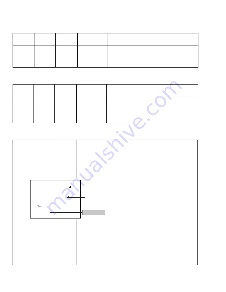
2. Select 1. IF from the SERVICE MENU.
3.
Press the 1 key to select 1. VCO.
4.
Select VCO ADJUST with the MENU
a
key and make sure
that the setup value shown in the screen is
+
00.
5.
Press the MENU
−
or
+
key until the colour of the characters
"TOO HIGH" displayed on the screen changes from blue to
yellow.
6.
Press the MENU
−
or
+
key until the colour of the characters
"TOO LOW" displayed on the screen changes from blue to
yellow. At this time, check that the value of VCO ADJUST on
the screen is +00 or about +00.
7.
Select AFT ADJUST with the MENU
a
key.
8.
Then, press the MENU
−
or
+
key until the colour of the char-
acters "JUST REFERENCE" displayed on the screen changes
from blue to yellow.
9.
Press the DISPLAY key three times to return to normal screen.
VCO (CW)
✽✽✽
.
✽✽
MHz
TOO HIGH
ABOVE REFERENCE
JUST REFERENCE
BELOW REFERENCE
TOO LOW
AFT ADJUST
✽✽✽
VCO ADJUST
✽✽✽
FINE
DISP : EXIT
fv
YELLOW
Do not adjust.


