No. 51908
23
AV-21L31
AV-25L31
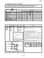
DEFLECTION CIRCUIT ADJUSTMENTS
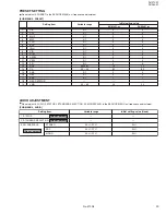
[SUB MENU 3. DEF]
1. VER. SLOPE
–31 — +31
+3
+6
+3
+6
—
2. VER. HEIGHT
–31 — +31
+31
+31
–28
–32
—
3. VER. POSITION
–31 — +31
–19
+6
–19
+6
—
4. VER. SCURVE
–31 — +31
–7
0
–7
0
—
5. HOR. POSITION
–31 — +31
+3
+6
+3
+6
+7
6. HOR. WIDTH
–31 — +31
+1
–2
+1
–2
—
7. EW-PIN
–31 — +31
+4
+1
–19
–18
—
8. EW-TRAPEZ
–31 — +31
–3
–4
–3
–4
—
9. UP CORNER
–31 — +31
+7
+2
–1
–1
—
10. DW CORNER
–31 — +31
+3
–1
–1
–1
—
11. HOR. PARALL
–31 — +31
+9
–1
+9
–1
—
12. HOR. BOW
–31 — +31
–3
0
–3
0
—
13. V.ZOOM
–31 — +31
–10
–12
+12
+14
—
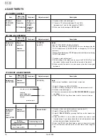
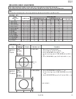
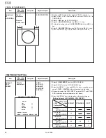
Item
Measuring
instrument
Test point
Adjustment part
Description
Adjustment
of
V. SLOPE
Signal
generator
Remote
control unit
1. VER. SLOPE
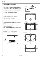
1. Receive a PAL circle pattern signal.
2. Select
3. DEF
from the SERVICE MENU.
3. Select
1. VER. SLOPE
with the MENU
&
/
^
key.
4. Set the initial setting value of
1. VER. SLOPE
with the MENU –/+
key.
5. Adjust
1. VER. SLOPE
to make “
A = B
” with the MENU –/+ key.
B
A
Blanking
line
Adjustment
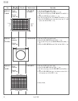
of
V. POSITION
Signal
generator
Remote
control unit
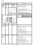
2. VER. POSITION
6. Select
2. VER. POSITION
with the MENU
&
/
^
key.
7. Set the initial setting value of
2. VER. POSITION
with the MENU
–/+ key.
8. Adjust
2. VER. POSITION
to make “
A = B
” with the MENU –/+ key.
(to be continued)
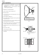
The setting (adjustment) using the remote control unit is made on the basis of the initial setting values.
The setting values which adjust the screen to the optimum condition can be different from the initial setting values.
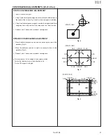
A
B
Note:
Proceed to the following adjustment after having completed the adjustments of SUB BRIGHT and SUB PICTURE.
[COMPRESS(16:9): OFF]
Initial setting value
Variable range
COMPONENT
21”
COMPRESS(16:9): ON
Setting
(Adjustment)
item
25”
COMPRESS(16:9): OFF
21”
25”
Содержание AV-21L31/ME
Страница 34: ...34 No 51908 AV 21L31 AV 25L31 SERVICE NOTE ...

