background image

E-11

English

LENS

DV

VIDEO OUT

TRGGER

REMORT

POWER

RGB, Y/C, SYNC OUT

DC IN

SEE INSTRUCTION MANUAL

10

12

11

13

14

15

16

17

0

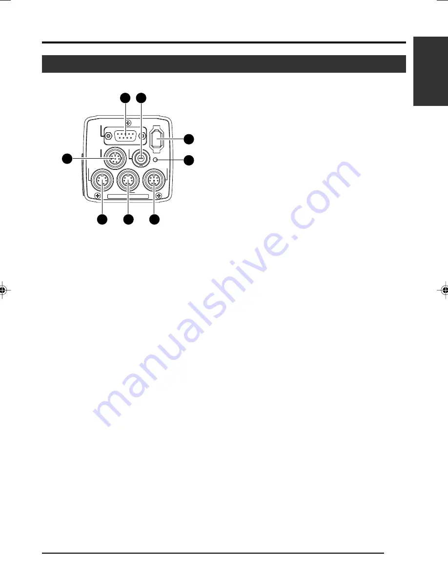
[RGB, Y/C, SYNC OUT] Analogue

Output Terminal

Output terminal for R/G/B, Y/C and composite
video/sync signal.

Page 10 ‘

9

 Function Setting Switch’

Page 13 ‘Description of Terminals’

Page 48 ‘Connecting the analogue output (D-
SUB) Cable’

!

[VIDEO OUT] Video Signal Output

Terminal

Output terminal for composite video signals.
Connect to video input terminals such as moni-
tors or switchers.

@

[DV] Digital Output Terminal

Digital output terminal for video. Connect this
terminal to computer’s [IEEE 1394] terminal or
[DV] terminal equipped video devices.

If this terminal is to be used, set Switch 1 lo-
cated at the side of this unit to [ON].

If this terminal is to be used to operate the
camera, set Switch 4 located at the side of
this unit to [ON].

Page 10 ‘

9

 Function Setting Switch’

Page 13 ‘Description of Terminals’

Page 48 ‘Connecting the IEEE 1394 Cable’

Part Names and Functions (continued)

#

[POWER] Power Indicator Light

Lights up when power is supplied to this unit.

$

[DC IN] Power Input Terminal

(Mini DIN 8 Pin, Female)
Power of this unit (DC 12 V) is supplied through
this terminal.
Use an AC adaptor (AA-P700) for the power
supply.

Page 12 ‘Description of Terminals’

Page 18 ‘Connecting the Power Supply’

%

[REMOTE] Remote Terminal

(Mini DIN 6 Pin, Female)
Terminal for connection to remote control unit
(RM-LP55 or RM-LP57, both sold separately).

Page 12 ‘Description of Terminals’

Page 46 ‘Connecting the Remote Control Unit’

^

[TRIGGER] Trigger Terminal

(Mini DIN 5 Pin, Female)
For inputting and outputting the various types of
timing signal when Slow Shutter or Random Trig-
ger function is used.

Page 12 ‘Description of Terminals’

Page 49 ‘Technical Information’

&

[LENS] Lens Connection Terminal

(Mini DIN 8 Pin, Female)
Connect the lens cable.

Page 12 ‘Description of Terminals’

Page 17 ‘Mounting the Lens’

Back

Содержание 3-CCD KY-F550

Страница 1: ... mit montiertem optionalem Objektiv Illustration avec objectif optionnel COLOUR VIDEO CAMERA FARBVIDEOKAMERA APPAREIL VIDEO EN COULEURS English Français Deutsch hank you for purchasing this JVC product efore operating this unit please read the nstructions carefully to ensure the best ossible performance LWT0159 001A ...

Страница 2: ......

Страница 3: ...used with 12 V DC only CAUTION To prevent electric shocks and fire hazards do NOT use any other power source CAUTION To prevent electric shock do not open the cabinet No user serviceable parts inside Refer servicing to qualified service personnel Note The rating plate serial number plate is on the bottom of the unit SAFETY PRECAUTIONS ...

Страница 4: ...necting Through Analogue Output 16 Mounting the Lens 17 Connecting the Power Supply 18 Mounting the Camera 19 Precautions to Prevent Camera From Falling 20 3 Setting and Adjustment During Shooting External Monitor Adjustment 21 White Balance Adjustment 22 White Shading Adjustment 24 4 Various Modes of Shooting Shooting the Computer Monitor 26 Output of Negative Image 27 White Spot Correction 28 ...

Страница 5: ... the Remote Control Unit 46 Connecting the IEEE 1394 Cable 48 Connecting the analogue output D SUB Cable 48 Technical Information 49 Specifications 50 Notations and Symbols Used in This Manual Caution Note Precautions during operation are stated Restrictions of functions and specifications are stated for reference purposes Indicates the page and item to refer to All product names in this manual ar...

Страница 6: ...er Accumulate up to 200 frames of image approximately 8 seconds Boosts the brightness of images dur ing shooting for objects with insufficient illumination and little motion Equipped with White Shading Function Corrects colour shading triggered by optical characteristics Black Stretch Black Compress Feature Stretches or compresses the gain of the dark section in an image to adjust the tone of that...

Страница 7: ...trong Electromagnetic Waves or Magnetism When placed near radios or TV transmitters or transformers and monitors that emit strong magnetism noise or colour change may occur in the image Ensure that this unit is kept away from the above during use Compatible Lens Page 17 Mounting the Lens Lens mount of this unit makes use of C mount and there are restrictions on the type of lens to be used Pay atte...

Страница 8: ...cket 3 Page 19 Mounting the Camera 3 Fastening Screws for Camera Mounting Bracket Supplied together with this unit M2 6 x 6 mm 2 pcs Caution Make sure to use screws that are supplied with this unit Use of screws that are 6 mm or longer in length may give rise to malfunction of the unit 4 Camera Mounting Screw Holes 1 4 20UNC Use when mounting this unit to fixer or swivel bases Use screws that are ...

Страница 9: ... screen is displayed Press these buttons to move between selection items on the menu screen Use the 5 button to move upwards Use the button to move downwards Used for altering the set values when an item is being selected 䡵 When the menu screen is off Press the AW button to adjust the white balance Page 22 White Balance Adjustment Press the AW button for 1 2 seconds to adjust the white shading Pag...

Страница 10: ... Switch 2 DSUB OUTPUT ON Y C signal will be output OFF RGB signal will be output Up Down Switch 3 SYNC ON GREEN ON Sync signal will be superimposed onto the Green G channel of the video signal output to the RGB Y C SYNC OUT terminal 0 OFF Sync signal will not be superim posed Switch 4 CONTROL MODE ON Operate the camera via DV termi nal IEEE1394 Operation via MENU SET 5 BARS AW buttons and the re m...

Страница 11: ...unit to ON Page 10 9 Function Setting Switch Page 13 Description of Terminals Page 48 Connecting the IEEE 1394 Cable Part Names and Functions continued POWER Power Indicator Light Lights up when power is supplied to this unit DC IN Power Input Terminal Mini DIN 8 Pin Female Power of this unit DC 12 V is supplied through this terminal Use an AC adaptor AA P700 for the power supply Page 12 Descripti...

Страница 12: ...IN 5 Pin Female TCS7858 Hoshiden Notes Please consult your JVC authorized dealer on connection of trigger terminal Ensure to use cables that are shielded Suitable Plug Mini DIN 5 PIN Signal NC GND NC NC GND 12 V Input NC 12 V Input Pin No 1 2 3 4 5 6 Signal GND OPERATE L ON GND SID2 TX SID1 RX 9 V Output Pin No 1 2 3 4 5 6 7 8 Signal LENS TYPE GND IRIS CONTROL 12 V Output SERVO SEL ZOOM CONTROL FO...

Страница 13: ...te Ensure to attach the supplied clamp filters to the cables connected to the Analogue Signal Output RGB Y C SYNC OUT terminal and Digital Output DV terminal in order to reduce unwanted electromagnetic emissions Page 48 Pin No 1 2 3 4 5 6 7 8 9 RGB Output GND GND R OUT G OUT B OUT Composite video OUT Composite sync OUT GND GND Pin No 1 2 3 4 5 6 7 8 9 Y C Output GND GND Y OUT C OUT Composite video...

Страница 14: ...nnect the DV terminal of this unit to the computer s DV IEEE1394 terminal 2 Set the Switch 1 and Switch 4 located at the side of this unit to ON upper side 3 Switch on the power of this unit 4 Set the DV SYSTEM under SYSTEM screen to JVC 5 Power on the computer and launch the software With the exclusive software provided it is possible to select the various camera settings and operate the camera f...

Страница 15: ...0 9800 or NVIDIA Quadro chip Card incorporated with YUV RGB conversion function is recommended DirectX 9 0 or later versions of Enduser Runtime 䡵 Suitable IEEE Host Adapter IEEE1394 host adapter card Matrox Meteor 2 1394 Ratoc REX CFW3 䡵 Compatible Lens Fujinon T14 X 5 5MD 䡵 Option AC Adapter AA P700 Using the exclusive software with other graphic cards and under PC environment other than above me...

Страница 16: ...unit s RGB Y C SYNC OUT terminal 2 Set the switches located at the side of this unit Setting Switch 2 Set this switch to ON upper side for Y C output Set this switch to OFF lower side for RGB output Setting Switch 3 Set this switch to ON upper side if sync sig nal is to be superimposed onto the Green G channel of the video signal Page 10 9 Function Setting Switch Example During RGB output 3 Switch...

Страница 17: ...and turn the mount fastening ring clockwise slowly until the lens is firmly attached to this unit Note To change the position of the lens rotation 1 First loosen the mount fastening ring by rotat ing it anti clockwise by 1 4 turn as viewed from the lens side 2 Turn the lens gently adjust the position and tighten the mount fastening ring again 2 Plug the lens cable into the LENS terminal at the bac...

Страница 18: ...e this unit is operable When the SHUTTER item under EXPOSURE screen is set to SLOW it might take even longer time Allow a 10 second interval after switching off the power before turning on again If the power switch is turned ON and OFF too soon malfunctioning such as startup failure may occur Connecting the Power Supply Connect the DC IN terminal at the back of this unit to the TO CAMERA terminal ...

Страница 19: ...ting Procedures Screw Hole for Mounting Camera Camera Mounting Bracket Anti rotation Hole Use the supplied camera mounting bracket and 2 fastening screws of the camera mounting bracket to mount it to the top or bottom surface Caution Make sure to use screws that are supplied with this unit Use of screws that are 6 mm or longer in length may give rise to malfunction of the unit Procedures for mount...

Страница 20: ...re place using safety cable to prevent it from falling To mount make use of the bracket fastening screw holes on the face without the cam era mounting bracket M2 6 x 4 mm Pay attention also to the length of the cable Strength of cable to prevent falling of unit shall be at least 10 times greater than the total mass of the camera and lens Safety cable to Prevent Falling of Equipment Camera Head 4 m...

Страница 21: ... a monochrome of blue and colour bars appear as blue stripes 4 Turn the CHROMA adjustment knob on the monitor and adjust colour bars 1 and 7 to the same brightness level 5 With BLUE CHECK in the ON mode turn the PHASE ad justment knob on the monitor to adjust colour bars 3 and 5 to the same brightness level 6 If brightness of colour bars 1 and 7 vary upon PHASE ad justment repeat chroma adjustment...

Страница 22: ...hen press the SET button 5 Press the MENU button for 1 2 seconds The normal screen will be displayed Note Upon returning to the normal screen place a white object with the same illumination conditions as the object zoom in to the white portion at the centre of the screen above 80 within the area 6 Press the AW Auto White button When auto white is activated the auto white operation area and AUTO WH...

Страница 23: ...n When this unit is set as below auto white cannot be activated When the SHUTTER item under EXPOSURE screen is set to SLOW When the MODE item under CAPTURE screen is set to RANDOM TRG When auto white shading is being activated If white balance is to be adjusted when processing frozen im age return to the normal screen before activating auto white 䡵 Full time Auto White FAW Function Automatic adjus...

Страница 24: ...CE then press the SET button The WHITE BALANCE screen will be displayed 3 Use the 5 buttons to select SHADING then press the SET button The set value starts blinking and adjustment is possible 4 Use the 5 buttons to set value to AUTO then press the SET button 5 Press the MENU button for 1 2 seconds The normal screen will be displayed Note After returning to normal screen shoot a white object to th...

Страница 25: ...ore activating auto white shading 7 Upon completing auto white shading adjustment perform white balance adjustment again Page 22 White Balance Adjustment White Shading Adjustment continued Object Error Excessive Illumination Insufficient Illumination Error Display When auto white shading adjustment is not correctly ended the following message will be displayed for about 3 seconds NG OBJECT Object ...

Страница 26: ...ttons to set value to V SCAN then press the SET button 5 Use the 5 buttons to select LEVEL then press the SET button 6 Use the 5 buttons to adjust the shutter speed Pay atten tion to the screen If black bands are visible use the button to lower the shutter speed If white bands are visible use the 5 button to increase the shutter speed 7 When bands are decreased to the minimum press the SET button ...

Страница 27: ... displayed 2 Use the 5 buttons to select SYSTEM then press the SET button The SYSTEM screen will be displayed 3 Use the 5 buttons to select NEGATIVE then press the SET button The set value starts blinking and adjustment is possible 4 Use the 5 buttons to set value to ON then press the SET button This will be recorded in the memory of this unit Output image will be converted to negative images 5 Pr...

Страница 28: ...to ensure that no light enters the CCD When using Galvano lens use lens cap to prevent light from entering the CCD SYSTEM Screen 2 3 4 5 SYSTEM Screen Blinking Blinking Preparation Make sure that the Switch 4 located at the side of this unit is set to OFF lower side 1 Press the MENU button for 1 2 seconds The MENU screen will be displayed 2 Use the 5 buttons to select SYSTEM then press the SET but...

Страница 29: ...s In such case perform the detection again until white spots are detected Consult your JVC authorized dealer if white spots cannot be corrected Quantity of Detection Correction 32 or less The screen on the right may be displayed during detection of white spots in cases when light enters the CCD during detection or depending on the condition of white spots In this case check if there is light enter...

Страница 30: ...Y C 0 8 1 LEVEL I P KNEE H W I TE CL LEVEL V CE WHI TE BALAN CE BALAN WH I TE AUTO1 0 0 LEVEL R LEVEL B LEVEL R LEVEL G LEVEL B S H AD I NG PAGE BACK CAPTURE MODE FREEZE RG T ALTERNATE I MAGE YPE T F I ELD RANDOM SHUT 1 5 0 FREEZE SYSTEM NEGAT I VE CANCEL F OF PEN I P XEL COM PRESET PAGE BACK DV SYSTEM JVC 5 Setting Via the Menu Screen Flow of Menu Screens MAIN MENU The menu screen is made up of m...

Страница 31: ... R F LARE B MASTER ADJUST PAGE BACK COLO MATR I X R FLARE BLACK 0 LEVEL TA S DARD N OR N AL M N O AN M AL U GAMMA At any displayed screen normal screen will be restored if MENU button is pressed for 1 2 sec onds When the remote control is connected items that can be operated via the remote control will be dis played as REMOTE on the menu screen Op eration of these items via the camera unit will be...

Страница 32: ...elect an item then press the SET button The set value starts blinking and adjustment is possible 6 Use the 5 buttons to alter the set value followed by press ing the SET button Set value will be confirmed and recorded in the memory of this unit Note If there is a huge difference in the magnitude of value to be set press and hold the 5 buttons to speed up the change Use this when making a significa...

Страница 33: ...ing the LEVEL item V GAIN Gain boost level can be fine tuned using the LEVEL item ALC Alters gain boost level automatically according to the brightness Set the maximum value at the ALC LIMIT item Page 35 Gain boost level can be altered when gain boost mode is set as STEP or V GAIN Variable STEP Values 3 0 3 6 9 12 15 18dB LOLUX Variable V GAIN Values 3 0 18dB 0 2dB Step Note When GAIN is set to AL...

Страница 34: ...00 1 10000 V SCAN variable Approx 1 50 approx 1 10000 Variable Values 1 frame 200 frame Notes When SHUTTER is set to EEI LEVEL item selection will be disabled Dis played as When the SHUTTER item is set to SLOW or when the MODE item under CAPTURE screen is set to RANDOM TRG the operation of auto white auto iris ALC and FAW will be as follows Auto White Startup of auto white is disabled Auto Iris Ch...

Страница 35: ...ng auto iris ALC or EEI Increase value Increases level Decrease value Decreases level Variable Values 5 0 5 Selects the detection method of the detection area when auto iris ALC or EEI is used NORMAL Normal Position PEAK Detects the maximum brightness value peak level to enhance visibility of objects with high luminance AVG Detects the average brightness value average to enhance visibility of obje...

Страница 36: ...rease value Decreases reddishness on screen Variable Values During AUTO 32 0 31 Variable Values During MANUAL 0 128 255 For adjusting the bluishness of white balance when WHITE BALANCE is set to AUTO or MANUAL Increase value Increases bluishness on screen Decrease value Decreases bluishness on screen Variable Values During AUTO 32 0 31 Variable Values During MANUAL 0 128 255 Item WHITE BALANCE LEV...

Страница 37: ...28 0 127 For adjusting greenishness of white shading only when the SHADING item is set to MANUAL Increase value Decreases greenishness at lower end and increases greenishness at upper end of screen Decrease value Decreases greenishness at upper end and increases greenishness at lower end of screen Variable Values 128 0 127 For adjusting bluishness of white shading only when the SHADING item is set...

Страница 38: ...0 For setting whether to emphasize the horizontal H or vertical V direction during contour highlight detail when DETAIL is set to ON Increase value Emphasize on H direction Decrease value Emphasize on V direction Variable Values 5 0 5 For altering the frequency for contour highlight detail when DETAIL is set to ON Set this according to the object LOW Lowers the frequency for contour highlight Use ...

Страница 39: ...e SHUTTER item under EXPOSURE screen is set to SLOW or when the MODE item under CAPTURE screen is set to RANDOM TRG it will change to MANUAL Press the SET button to invoke the PROCESS 2 2 screen when the cursor is at this position Page 40 PROCESS 2 2 Screen Press the SET button to return to the MENU screen when cursor is at this position Item WHITE CLIP KNEE LEVEL NEXT PAGE PAGE BACK Settings in b...

Страница 40: ...5 0 5 Note Displayed as when the GAMMA item is set to OFF For switching gain of the dark portions Switch via the video signals to be shot NORMAL Standard mode STRETCH Stretches only the darker portions of the signal thus emphasizing the light and shade of the darker portions COMPRESS Compresses gain of the black portion to add contrast in the case when image shot is bright and with little contrast...

Страница 41: ... of Bch to reduce the bluishness Variable Values 10 0 10 Press the SET button to return to the PROCESS 1 2 screen when cursor is at this position PROCESS 2 2 Screen continued Settings in bold are factory settings Item NEGATIVE PIXEL COMPEN DV SYSTEM PAGE BACK Function Variable Values Signals from the various output terminals can be output as negative signals ON Outputs negative signals OFF Outputs...

Страница 42: ...e value Enhances green and magenta Decrease value Reduces green and magenta Variable Values 3 0 3 For manually adjusting the colour phase of the G axis of the colour matrix green and magenta Increase value Increases bluishness of green colour and reddishness of magenta colour Decrease value Increases yellowishness of green colour and bluishness of magenta colour Variable Values 3 0 3 For manually ...

Страница 43: ...gering input Setting the output signals according to the trigger inputs ALTERNATE Alternating between freeze and release with every trigger input MOMENTARY New frozen image is output to replace the previous one with every trigger input Note When MODE item is set to RANDOM TRG it is fixed to MOMENTARY and MOMENTARY is displayed For setting the FREEZE mode FIELD Freezes a field image FRAME Freezes a...

Страница 44: ...nking Blinking Blinking 5 Setting Via the Menu Screen continued Display the FILE MANAGE screen Make sure that the Switch 4 located at the side of this unit is set to OFF lower side 1 Press the MENU button for 1 2 seconds The MENU screen will be displayed 2 Use the 5 buttons to select FILE MANAGE then press the SET button The FILE MANAGE screen will be displayed Save the set value 1 Use the 5 butto...

Страница 45: ...Use the 5 buttons to select LOAD then press the SET button CANCEL will start to blink 4 Use the 5 buttons to select EXECUTE followed by pressing the SET button to retrieve the menu settings from the selected file destination Reset the set value 1 Use the 5 buttons to select RESET FILE then press the SET button The set value displayed will start to blink 2 Use the 5 buttons to select a file to rese...

Страница 46: ...hite shading is being activated through the camera operation When the RANDOM TRIGGER function is set to OFF the camera operates in FREEZE mode Notes In the case when the menu function of this unit is identical to the remote control unit the switch func tion of the local remote control will override that of this unit When connected to RM LP55 even if the V SCAN under SHUTTER item is set to 1 50 0 t...

Страница 47: ...O WHITE SHADING RANDOM TRIGGER SLOW SHUTTER Operation From RM LP57 CAM BARS ON LEVEL OFF AUTO LEVEL MANU AUTO1 AUTO2 FAW AUTO1 AUTO2 0 6 9 12 18 dB ALC ALC EEI NORMAL 1 120 1 250 1 500 1 1000 1 2000 EEI 1 1 Operation From RM LP55 BARS CAM NEGA ON LEVEL OFF LEVEL AUTO LEVEL MANU NORMAL PEAK AVG AUTO1 AUTO2 FAW MANUAL PRESET AUTO1 AUTO2 3 0 6 9 12 18 dB ALC ALC EEI LOLUX NORMAL 1 120 1 250 1 500 1 1...

Страница 48: ...r as shown in the diagram on the left to reduce unwanted electro magnetic emission Attach the clamp filter as shown in the diagram on the left to this unit as near as possible Set the switches located at the side of this unit Setting Switch 2 Set this switch to ON upper side for Y C output Set this switch to OFF lower side for RGB output Setting Switch 3 Set this switch to ON upper side if sync si...

Страница 49: ...lly It is accomplished by accumulating charges stored in the CCD imaging device In addition by lengthening the duration for accumulating charges more charges could be stored in the CCD and hence allowing high sensitivity images to be taken under low lighting condition The maximum accumulation timing is up till 200 frames approx 8 seconds Random Trigger Function For verifying the image of a fast mo...

Страница 50: ...e by switch RGB Signal 0 7 V p p 75 1 V p p 75 when SYNC ON G With Colour Bars Y Signal 1 V p p 75 With Colour Bars C Signal Burst level 0 3 V p p 75 SYNC Signal 2 V p p 75 DV Signal DV Specification All signal types can be superimposed on characters Dynamic Range 400 and above Gain Boost 3 0 3 6 9 12 15 18 dB ALC LOLUX V GAIN Electronic Shutter STEP 1 6 25 1 12 5 1 25 NORMAL 1 50 1 120 1 250 1 50...

Страница 51: ...UTO1 AUTO2 FAW MANUAL PRESET Compliance Range 2300 K 10000 K DV Terminal IEEE1394 6 Pin Connector Cable with lock feature can be used Temperature Range During Use 5 C 40 C Humidity of 80 or lower Transport and Storage Condition Temperature 20 C 60 C Humidity 85 RH or lower Input Supply Voltage DC 12 V When using AA P700 DC 8 V DC 33 V When using IEEE 1394 Cable Power Consumption 12 V 0 7 A Dimensi...

Страница 52: ...E 52 Memo ...

Страница 53: ...Deutsch KY F550 BEDIENUNGSANLEITUNG FARBVIDEOKAMERA ...

Страница 54: ...d darf in den folgenden Umgebungen betrieben werden 5 Wohngebiete in Wohnräumen einschließlich von Orten der Klasse 1 und 2 IEC 1000 2 5 5 Gewerbe und Leichtindustriegebiete wie z B in Aufführungsräumen 5 Im Freien im Stadtgebiet basierend auf der Definition von Ortstypen der Klasse 6 IEC 1000 2 5 Dieses Gerät ist zum Gestelleinbau und zum Betreiben in unmittelbarer Nähe anderer Geräte und Vorrich...

Страница 55: ...chstrom verwendet werden ACHTUNG Zur Verhütung von Feuer und elektrischem Schlag keine andere Stromquelle verwenden ACHTUNG Zur Verhütung von elektrischem Schlag nicht dasGehäuseöffnen EssindkeinevomBenutzer wartbare Teile im Inneren Wartung durch qualifiziertes Personal durchführen lassen Hinweis Das Geräteschild Seriennummernschild befindet sich auf dem Gehäuseboden SICHERHEITSHINWEISE ...

Страница 56: ...talausgang 14 Anschluss über den Analogausgang 16 Objektiv montieren 17 Netzteil anschließen 18 Kamera montieren 19 Vorsichtsmaßnahmen gegen Sturzgefahr 20 3 Einstellungen während des Aufnahmevorgangs Externen Monitor einstellen 21 Weißabgleich einstellen 22 White Shading einstellen 24 4 Aufnahmemodi Computermonitor aufnehmen 26 Ausgabe eines Negativbildes 27 Weißpunktkorrektur 28 ...

Страница 57: ...abel anschließen 48 Analogausgangskabel D Sub anschließen 48 Technische Hinweise 49 Technische Daten 50 In dieser Anleitung verwendete Hinweise und Symbole Vorsicht Hinweis Verweist auf Sicherheitsmaßregeln die während des Betriebs zu beachten sind Bezeichnet Funktions oder Einsatzbeschränkungen dieses Geräts Diese Hinweise haben lediglich informierenden Charakter Verweist auf Seitenzahlen oder Be...

Страница 58: ...ngszeit Speichert bis zu 200 Bilder ca 8 Sekunden Verstärkt während der Aufnahme die Helligkeit von Objek ten bei unzureichender Ausleuchtung oder Bewegung White Shading Funktion Korrigiert die Farbschattierung nach optischen Eigenschaften Schwarzdehnung kompression Dehnt oder komprimiert die Stärke der dunklen Bereiche eines Bildes um den Farbton dieses Bereichs einzustellen Negativanzeige Wird f...

Страница 59: ... das Gerät in der Nähe von Radio oder TV Geräten Transformatoren oder Monitoren aufgestellt wird die starke magnetische Felder erzeugen können Bildrauschen oder Farbveränderungen auftreten Stellen Sie deswegen sicher dass das Gerät im Betrieb nicht in der Nähe der genannten Einrichtungen steht Kompatible Objektive Seite 17 Objektiv montieren Der Objektivadapter dieses Geräts ist als C Mount Adapte...

Страница 60: ... 3 Befestigungsschrauben für Kameramontagehalterung Im Lieferumfang enthalten M2 6 x 6 mm 2 Stück Vorsicht Verwenden Sie zur Montage ausschließlich die diesem Gerät beiliegenden Schrauben Die Ver wendung von Schrauben mit einer Länge von 6 mm oder mehr kann Fehlfunktionen am Gerät hervorrufen 4 Bohrungen für Kameramontage 1 4 20UNC Verwenden Sie diese Bohrungen zur Montage auf einem Stativ Verwend...

Страница 61: ...chen den einzelnen Elementen auf dem Menübildschirm wechseln Mit der Taste 5 bewegen Sie sich nach oben Mit der Taste bewegen Sie sich nach unten Ist ein Parameter selektiert dann können Sie dessen Wert mit diesen Tasten ändern 䡵 Bei abgeschaltetem Menübildschirm Betätigen Sie die AW Taste Auto White um den Weißabgleich zu justieren Seite 22 Weißabgleich einstellen Betätigen Sie die AW Taste Auto ...

Страница 62: ... eines Y C Signals OFF Ausgabe eines RGB Signals Oben Unten Schalter 3 Sync im G Kanal ON Das Synchronisationssignal wird in den G Kanal Grün des Videosig nals am RGB Y C SYNC OUT Ausgang 0 eingebettet OFF Es wird kein Synchronisationssignal ausgegeben Schalter 4 Steuermodus ON Die Kamera wird über den DV An schluss IEEE1394 bedient In diesem Fall ist eine Bedienung durch die Tasten MENU SET und 5...

Страница 63: ...aben Seite 10 9 Funktionsschalter Seite 13 Beschreibung der Anschlüsse Seite 48 IEEE 1394 Kabel anschließen Bedienelemente und Funktionen Fortsetzung POWER Anzeige Diese Anzeige leuchtet wenn das Gerät an das Stromnetz angeschlossen ist DC IN Buchse Anschlussbuchse für das Netzkabel 8 polige Mini DIN Buchse Female Über diesen Anschluss wird das Gerät mit der benötigten Betriebsspannung 12 VDC vers...

Страница 64: ...en zum Anschluss einer Auslöser konsole an den TRIGGER Anschluss erhalten Sie bei Ihrem JVC Händler Verwenden Sie ausschließlich geschirmte Kabel Geeigneter Stecker 5 poliger Mini DIN Stecker Signal NC GND NC NC GND 12 V Eingangsspannung NC 12 V Eingangsspannung Kontakt Nr 1 2 3 4 5 6 Signal GND OPERATE L ON GND SID2 TX SID1 RX 9 V Ausgangsspannung Kontakt Nr 1 2 3 4 5 6 7 8 Signal LENS TYPE GND I...

Страница 65: ...ntieren Sie die beiliegenden Filterklammern an die Kabel die mit den analogen und digitalen Ausgangsanschlüssen RGB Y C SYNC OUT bzw DV verbunden sind Auf diese Weise können Sie unerwünschte elektromagnetische Einstreuungen verringern Seite 48 Kontakt Nr 1 2 3 4 5 6 7 8 9 RGB Ausgang GND GND R OUT G OUT B OUT Composite Video OUT Composite Sync OUT GND GND Kontakt Nr 1 2 3 4 5 6 7 8 9 Y C Ausgang G...

Страница 66: ...eordneten Schalter 1 und 4 auf ON obere Position 3 Schalten Sie das System ein 4 Weisen Sie dem Parameter DV SYSTEM auf dem SYSTEM Bildschirm die Einstellung JVC zu 5 Schalten Sie den Computer ein und starten Sie die Software Mithilfe der beiliegenden Spezialsoftware können Sie verschiedene Kameraeinstellungen auswählen und die Aufnahme mit der Kamera steuern Weitere Informationen hierzu erhalten ...

Страница 67: ... NVIDIA Quadro Chip Grafikkarte mit integrierter YUV RGB Konvertierung empfohlen DirectX Version 9 0 oder höher der Enduser Runtime Dateien 䡵 Geeigneter IEEE Hostadapter IEEE1394 Hostadapterkarte Matrox Meteor 2 1394 Ratoc REX CFW3 䡵 Kompatibles Objektiv Fujinon T14 X 5 5MD 䡵 Optionen AC Netzteil AA P700 Die Verwendung der Spezialsoftware mit anderen Grafikkarten und oder in anderen als den beschr...

Страница 68: ... dieses Geräts an 2 Stellen Sie die seitlich angeordneten Schalter wie nachfolgend beschrieben ein Einstellung Schalter 2 Zur Y C Ausgabe schieben Sie diesen Schal ter in die Position ON obere Stellung Zur RGB Ausgabe schieben Sie diesen Schal ter in die Position OFF untere Stellung Einstellung Schalter 3 Stellen Sie diese Schalter auf ON wenn das Synchronisationssignal in den G Kanal Grün des Vid...

Страница 69: ...ngsam im Uhrzeigersinn bis das Objektiv fest auf der Kamera sitzt Hinweis Gehen Sie wie folgt vor um die Objektivdrehrichtung zu ändern 1 Lösen Sie zunächst den Verschlussbefestigungs ring indem Sie ihn aus Objektivrichtung gese hen um eine Vierteldrehung gegen den Uhrzei gersinn drehen 2 Drehen Sie das Objektiv vorsichtig stellen Sie die Position ein und ziehen Sie den Verschluss befestigungsring...

Страница 70: ...eit ist Wenn der Parameter SHUTTER im EXPOSURE Bildschirm die Einstellung SLOW hat kann es noch länger dauern Warten Sie nach dem Abschalten des Netzschalters mindestens zehn Sekunden bevor Sie das Netzteil wieder einschalten Wird der Netzschalter zu schnell hintereinander aus und eingeschaltet dann kann es zu Fehlfunktionen beim Einschalten kommen Netzteil anschließen Verbinden Sie den DC IN Ansc...

Страница 71: ... für Kameramontage Kameramontagehalterung Arretieröffnung Montieren Sie die beiliegende Kameramontagehalterung mithilfe der beiden zugehörigen Schrauben auf die Ober oder Unterseite Vorsicht Verwenden Sie zur Montage ausschließlich die diesem Gerät beiliegenden Schrauben Die Verwendung von Schrauben mit einer Länge von 6 mm oder mehr kann Fehlfunktionen am Gerät hervorrufen Vorgehensweise zur Mont...

Страница 72: ...e des Sicherheitskabels an einem sicheren Ort um ein Herabfallen zu verhindern Verwenden Sie zur Absicherung die freien Bohrun gen auf der Seite auf der die Kameramontagehalterung nicht montiert ist M2 6 x 4 mm Achten Sie auch auf die Länge des Drahtseils Es sollte stark genug sein um das Herabfallen einer Masse zu verhindern die zehn mal größer ist als das Gesamtgewicht von Kamera und Objektiv Si...

Страница 73: ...tbild werden als blaue Streifen dargestellt 4 Stellen Sie die Farbfelder 1 und 7 mit dem CHROMA Reg ler am Monitor auf die gleiche Helligkeit ein 5 Während BLUE CHECK weiterhin auf ON steht stellen Sie den PHASE Regler so ein dass die Farbfelder 3 und 5 die gleiche Helligkeit aufweisen 6 Wenn die Helligkeit der Farbfelder 1 und 7 sich bei Betäti gung des PHASE Reglers ebenfalls ändern wiederholen ...

Страница 74: ... für ein bis zwei Sekunden Der normale Bildschirm wird angezeigt Hinweis Wenn der normale Bildschirm wieder angezeigt wird tauschen Sie das Objekt gegen ein weißes Objekt aus ohne die Beleuch tung zu ändern und zoomen Sie dann auf einen weißen Bereich in der Mitte des Bildschirms über 80 im Bereich 6 Betätigen Sie die AW Taste Auto White Wenn der automatische Weißabgleich aktiviert ist werden der ...

Страница 75: ...arameter SHUTTER im EXPOSURE Bildschirm die Einstellung SLOW hat Wenn der Parameter MODE im CAPTURE Bildschirm die Einstellung RANDOM TRG hat Wenn das automatische White Shading aktiviert wurde Wenn das Standbild aktiviert ist und der Weißabgleich einge stellt werden soll kehren Sie zum normalen Bildschirm zurück bevor Sie den automatischen Weißabgleich aktivieren 䡵 FAW Funktion Fulltime Auto Whit...

Страница 76: ...angezeigt 3 Wählen Sie mit den Tasten 5 den Parameter SHADING und betätigen Sie dann die SET Taste Der eingestellte Wert blinkt und kann nun geändert werden 4 Wählen Sie mit den Tasten 5 die Einstellung AUTO und betätigen Sie die SET Taste 5 Betätigen Sie die MENU Taste für ein bis zwei Sekunden Der normale Bildschirm wird angezeigt Hinweis Wenn wieder der normale Bildschirm angezeigt wird nehmen ...

Страница 77: ...chirm zurück be vor Sie das automatische White Shading aktivieren 7 Wenn Sie die automatische Einstellung des White Shadings vorgenommen haben müssen Sie den Weißabgleich erneut durchführen Seite 22 Weißabgleich einstellen White Shading einstellen Fortsetzung Objektfehler übermäßige Beleuchtung unzureichende Beleuchtung Fehleranzeige Kann das automatische White Shading nicht korrekt durchgeführt w...

Страница 78: ...Sie die SET Taste 5 Wählen Sie mit den Tasten 5 den Parameter LEVEL und betätigen Sie dann die SET Taste 6 Stellen Sie die Belichtungszeit mit den 5 Tasten ein Be trachten Sie dabei den Bildschirm Wenn schwarze Bänder zu sehen sind Verringern Sie die Belichtungszeit mit der Taste Wenn weiße Bänder zu sehen sind Erhöhen Sie die Belichtungszeit mit der 5 Taste 7 Sind keine Bänder mehr zu sehen dann ...

Страница 79: ...den Tasten 5 die Funktion SYSTEM und betätigen Sie dann die SET Taste Der SYSTEM Bildschirm wird angezeigt 3 Wählen Sie mit den Tasten 5 den Parameter NEGATI VE und betätigen Sie dann die SET Taste Der eingestellte Wert blinkt und kann nun geändert werden 4 Wählen Sie mit den Tasten 5 die Einstellung ON und betätigen Sie die SET Taste Die Einstellung wird im Gerät gespeichert Das Ausgabebild wird ...

Страница 80: ...ein Licht auf das CCD fällt Wenn Sie ein Galvanoobjektiv benut zen verwenden Sie den Objektivaufsatz um zu verhindern dass Licht in das CCD fällt SYSTEM Bildschirm 2 3 4 5 SYSTEM Bildschirm Blinkt Blinkt Vorbereitung Stellen Sie sicher dass der seitlich angeordnete Schalter 4 auf OFF untere Stellung steht 1 Betätigen Sie die MENU Taste für ein bis zwei Sekunden Der MENU Bildschirm wird angezeigt 2...

Страница 81: ... Fällen die Erkennung erneut durch bis die weißen Punkte gefunden werden Ist eine Weißpunktkorrektur nicht möglich dann wenden Sie sich an Ihren JVC Händler Anzahl Erkennung Korrektur maximal 32 Die rechts abgebildete Meldung kann wenn während der Erkennung der weißen Punkte Licht auf das CCD fällt oder abhängig von der Beschaf fenheit der weißen Punkte angezeigt werden Prüfen Sie in diesem Fall o...

Страница 82: ... CE WHI TE BALAN CE BALAN WH I TE AUTO1 0 0 LEVEL R LEVEL B LEVEL R LEVEL G LEVEL B S H AD I NG PAGE BACK CAPTURE MODE FREEZE RG T ALTERNATE I MAGE YPE T F I ELD RANDOM SHUT 1 5 0 FREEZE SYSTEM NEGAT I VE CANCEL F OF PEN I P XEL COM PRESET PAGE BACK DV SYSTEM JVC 5 Einstellungen über den Menübildschirm Abfolge der Menübildschirme MENU Bildschirm Das Menü besteht aus mehreren Ebenen von Menübildsch...

Страница 83: ...ie Bedienung solcher Parameter über die Kamera deaktiviert Abfolge der Menübildschirme Fortsetzung Seite 35 Seite 35 Seite 40 Seite 42 ALC L I M I T 18 dB 0 EE I M I L NO L A M R I T AE E LEV L AE A ARE AE DETEC ADVANCED T EXPOSURE BACK PAGE 2 0 1 0 R GA I N 0 R R T A T O ION MATRI X ADJUST BACK PAGE 0 G GA I N 0 0 0 0 G R T A T O ION 0 B GA I N 0 B R T A T O ION 0 NORMAL PROCESS 2 2 F LARE R F LA...

Страница 84: ...lte Wert blinkt und kann nun geändert werden 6 Mit den Tasten 5 können Sie den Wert ändern und die Änderung dann mit der SET Taste bestätigen Der gewähl te Wert wird übernommen und im Speicher des Geräts abge legt Hinweis Bei umfangreichen Werteänderungen können Sie die Tasten 5 gedrückt halten um die Änderung zu beschleunigen Verwenden Sie diese Funktionalität wenn Sie Werte deutlich ändern wolle...

Страница 85: ...s Parameters LEVEL geändert werden V GAIN Die Verstärkung kann mithilfe des Parameters LEVEL feinabgestimmt werden ALC Ändert die Verstärkung automatisch abhängig von der Helligkeit Den Höchstwert stellen Sie mit dem Parameter ALC LIMIT ein Seite 35 Der Verstärkungsgrad kann geändert werden wenn hier einer der Modi STEP oder V GAIN eingestellt wird Einstellbereich STEP 3 0 3 6 9 12 15 18dB LOLUX E...

Страница 86: ...a 1 10000 Einstellbereich 1 200 Bilder Hinweise Wenn für SHUTTER die Einstellung EEI gewählt wurde ist die Auswahl des Parameters LEVEL deaktiviert Wird angezeigt als Wenn der Parameter SHUTTER die Einstellung SLOW oder der Parameter MODE auf dem CAPTURE Bildschirm die Einstellung RANDOM TRG hat arbeiten die Funktionen auto white auto iris ALC und FAW wie folgt Auto White Die Funktion kann nicht g...

Страница 87: ...EI ein Erhöhung des Werts Pegelerhöhung Verringerung des Werts Pegelverringerung Einstellbereich 5 0 5 Hier wählen Sie die Erkennungsmethode für den Erkennungsbereich zur Verwen dung durch die Funktionen auto iris ALC oder EEI NORMAL Normalposition PEAK Erkennt den höchsten Helligkeitswert um die Sichtbarkeit von Objekten mit hoher Lichtstärke zu verbessern AVG Erkennt den Durchschnittswert der He...

Страница 88: ... Rotanteil am Bildschirm Einstellbereich bei AUTO 32 0 31 Einstellbereich bei MANUAL 0 128 255 Dient der Einstellung des Blauanteils im Weißabgleich wenn der Parameter WHITE BALANCE die Einstellungen AUTO oder MANUAL hat Erhöhung des Werts Erhöht den Blauanteil am Bildschirm Verringerung des Werts Verringert den Blauanteil am Bildschirm Einstellbereich bei AUTO 32 0 31 Einstellbereich bei MANUAL 0...

Страница 89: ...ng des Grünanteils beim White Shading wenn SHADING die Einstellung MANUAL hat Erhöhung des Werts Verringert den Grünanteil am unteren Rand des Bildschirms und erhöht ihn am oberen Rand Verringerung des Werts Verringert den Grünanteil am oberen Rand des Bildschirms und erhöht ihn am unteren Rand Einstellbereich 128 0 127 Erlaubt die Einstellung des Blauanteils beim White Shading wenn SHADING die Ei...

Страница 90: ...r legen Sie fest ob während der Konturbetonung wenn DETAIL die Einstel lung ON hat die horizontale oder vertikale Richtung betont wird Erhöhung des Werts Betont die horizontalen Konturen Verringerung des Werts Betont die vertikalen Konturen Einstellbereich 5 0 5 Hier ändern Sie die Frequenz für die Konturen Details wenn DETAIL die Ein stellung ON hat Nehmen Sie die Einstellung je nach Objekt vor L...

Страница 91: ...ameter MODE auf dem CAPTURE Bildschirm die Einstellung RANDOM TRG hat Betätigen Sie wenn sich der Cursor an dieser Position befindet die SET Taste um den PROCESS 2 2 Bildschirm aufzurufen Seite 40 PROCESS 2 2 Bildschirm Betätigen Sie wenn sich der Cursor an dieser Position befindet die SET Taste um wieder zum MENU Bildschirm zurückzukehren Parameter WHITE CLIP KNEE LEVEL NEXT PAGE PAGE BACK Fett g...

Страница 92: ...er GAMMA die Einstellungen OFF hat Hier aktivieren Sie die Verstärkung der dunklen Bereiche Nehmen Sie die Ein stellung entsprechend den aufzunehmenden Videosignalen vor NORMAL Standardmodus STRETCH Dehnt nur die dunkleren Bereiche des Signals und betont auf diese Weise Licht und Schatten in diesen Bereichen COMPRESS Komprimiert die Verstärkung der dunklen Bereiche und verstärkt auf diese Weise de...

Страница 93: ...Blaukanal und damit auch den Blauanteil Einstellbereich 10 0 10 Betätigen Sie wenn sich der Cursor an dieser Position befindet die SET Taste um wieder zum PROCESS 1 2 Bildschirm zurückzukehren PROCESS 2 2 Bildschirm Fortsetzung Fett gedruckte Werte sind Werksvoreinstellungen Parameter NEGATIVE PIXEL COMPEN DV SYSTEM PAGE BACK Funktion Parameterwerte Die über die verschiedenen Ausgänge gesendeten S...

Страница 94: ... Verstärkt die Farben Grün und Magenta Verringerung des Werts Dämpft die Farben Grün und Magenta Einstellbereich 3 0 3 Dient der manuellen Einstellung der Farbphase der G Achse der Farbmatrix Grün und Magenta Erhöhung des Werts Erhöht den Blauanteil der Farbe Grün und den Rotanteil der Farbe Magenta Verringerung des Werts Erhöht den Gelbanteil der Farbe Grün und den Blauanteil der Farbe Magenta Ei...

Страница 95: ...chen Stand und Normalbild MOMENTARY Bei jedem Auslöserimpuls wird ein neues Standbild angezeigt welches das vorherige ersetzt Hinweis Wenn der Parameter MODE die Einstellung RANDOM TRG hat ist hier die Ein stellung MOMENTARY festgelegt In diesem Fall wird die Einstellung als MOMENTARY angezeigt Stellt den FREEZE Modus ein FIELD Zeigt ein Feldbild als Standbild FRAME Zeigt ein Einzelbild als Standb...

Страница 96: ... Menübildschirm Fortsetzung FILE MANAGE Bildschirm aufrufen Stellen Sie sicher dass der seitlich angeordnete Schalter 4 auf OFF untere Stellung steht 1 Betätigen Sie die MENU Taste für ein bis zwei Sekunden Der MENU Bildschirm wird angezeigt 2 Wählen Sie mit den Tasten 5 die Funktion FILE MANA GE und betätigen Sie dann die SET Taste Der FILE MANAGE Bildschirm wird angezeigt Einstellungen speichern...

Страница 97: ...sten 5 die Funktion EXECUTE aus und betätigen Sie dann die SET Taste um die Menü einstellungen der gewählten Datei zu laden Werkseinstellungen wiederherstellen 1 Wählen Sie mit den Tasten 5 die Funktion RESET FILE und betätigen Sie dann die SET Taste Der angezeigte Wert blinkt 2 Wählen Sie mit den Tasten 5 die Datei in der Sie die Einstellungen wiederherstellen wollen und betätigen Sie dann die SE...

Страница 98: ...die Einstellung ON hat Wenn das automatische White Shading über den Kamerabetrieb aktiviert wird Wenn die Funktion RANDOM TRIGGER die Ein stellung OFF hat läuft die Kamera im Standbild modus FREEZE Hinweise Wenn die Menüfunktionen dieses Geräts mit de nen der lokalen Fernbedienung identisch sind hat die Fernbedienung bei der Steuerung Vorrang vor den Bedienelementen dieses Geräts Bei Verbindung mi...

Страница 99: ...HI RESO WHITE SHADING RANDOM TRIGGER SLOW SHUTTER über RM LP57 CAM BARS ON LEVEL OFF AUTO LEVEL MANU AUTO1 AUTO2 FAW AUTO1 AUTO2 0 6 9 12 18 dB ALC ALC EEI NORMAL 1 120 1 250 1 500 1 1000 1 2000 EEI 1 1 über RM LP55 BARS CAM NEGA ON LEVEL OFF LEVEL AUTO LEVEL MANU NORMAL PEAK AVG AUTO1 AUTO2 FAW MANUAL PRESET AUTO1 AUTO2 3 0 6 9 12 18 dB ALC ALC EEI LOLUX NORMAL 1 120 1 250 1 500 1 1000 1 2000 V S...

Страница 100: ... elektromagnetische Einstreuungen zu verringern Montieren Sie die Filter dabei wie abgebildet so nah am Gerät wie möglich Stellen Sie die seitlich angeordneten Schalter wie nachfolgend beschrieben ein Einstellung Schalter 2 Zur Y C Ausgabe schieben Sie diesen Schalter in die Position ON ubere Stellung Zur RGB Ausgabe schieben Sie diesen Schalter in die Position OFF untere Stellung Einstellung Scha...

Страница 101: ...n Die Funktion wird nicht über eine elektronische Verstärkung realisiert Vielmehr werden die Ladungen im CCD Aufnahmemedium gespeichert Außerdem wird die Dauer der Ladungsspeicherung verlängert so dass mehr Ladungen im CCD gespeichert und so hochempfindliche Bilder auch bei schlechter Beleuch tung aufgenommen werden können Die maximale Akkumulationsdauer beträgt bis zu 200 Bilder ca 8 Sekunden Die...

Страница 102: ...nal Auswahl über Schalter RGB Signal 0 7 V p p 75 1 V p p 75 bei SYNC ON G mit Farbfeldern Y Signal 1 V p p 75 mit Farbfeldern C Signal Burst Pegel 0 3 V p p 75 SYNC Signal 2 V p p 75 DV Signal DV Spezifikation Alle Signaltypen können Zeichen überlagern Dynamikbereich 400 und besser Verstärkung 3 0 3 6 9 12 15 18 dB ALC LOLUX V GAIN Elektronische Belichtungszeit STEP 1 6 25 1 12 5 1 25 NORMAL 1 50...

Страница 103: ...peratur 5 C bis 40 C Luftfeuchtigkeit 80 max Zulässige Aufbewahrungstemperatur 20 C bis 60 C Zulässige Aufbewahrungsluftfeuchtigkeit 85 max Betriebsspannung 12 VDC beim Einsatz von AA P700 8 33 VDC beim Einsatz eines IEEE 1394 Kabels Leistungsaufnahme 12 V 0 7 A Abmessungen B x H x T 67 5 x 64 x 80 5 mm ohne Anschlussstecker Gewicht 380 g nur Gerät Beiliegendes Zubehör Netzkabel 8P 2 m x 1 Kameram...

Страница 104: ...G 52 Memo ...

Страница 105: ...Français KY F550 MODE D EMPLOI APPAREIL VIDEO EN COULEURS ...

Страница 106: ...ER Câble exclusif 5 mètres REMOTE Câble exclusif 5 mètres DV Câble exclusif 4 5 mètres DC IN Câble exclusif 2 mètres PRECAUTIONS DE SECURITE F 2 Ce matériel est en conformité avec les prescriptions et exigences relatives à la sécurité des directives européennes correspondantes Il est conçu pour des applications vidéo professionnelles et peut être utilisé dans les milieux suivants 5 zone résidentie...

Страница 107: ...ION Afin d éviter tout risque d électrocution et d incendie n utilisez AUCUNE autre source d alimentation ATTENTION Afind évitertoutrisqued électrocution n ouvrez pas le coffret Aucun élément interne n est à régler par l utilisateur Se référer à un agent qualité en cas de problème REMARQUE La plaque signalétique plaque du numéro de série est située sur le cadre inférieur de l unité PRECAUTIONS DE ...

Страница 108: ...gique 16 Montage de l objectif 17 Connexion du bloc d alimentation 18 Montage de l appareil 19 Précautions à prendre pour ne pas faire tomber l appareil 20 3 Réglage et ajustement pendant la prise Ajustement du moniteur externe 21 Ajustement de l équilibre des blancs 22 Ajustement de l ombrage des blancs 24 4 Divers modes de prise Prise du moniteur de l ordinateur 26 Sortie d une image négative 27...

Страница 109: ...n du câble de sortie analogique D SUB 48 Information technique 49 Caractéristiques techniques 50 Annotations et symboles utilisés dans le présent manuel Attention Remarque Les précautions à prendre pendant l utilisation sont stipulées Les restrictions applicables aux fonctions et aux carctéristiques techniques sont indiquées à titre de référence Indique la page ou l élément à référencer Les noms d...

Страница 110: ...d image environ 8 secondes Dynamise la luminosité des images pen dant la prise d objets avec un éclairement insuffisant et un léger mouvement Doté d une fonction d ombrage des blancs Rectifie l ombrage des couleurs résultants des caractéristiques optiques Caractéristique de suramplification compression du noir Suramplifie ou compresse le gain de la section noire sur une image pour ajuster le ton d...

Страница 111: ...iques puissantes ou magnétisme Lorsque l appareil est placé près d émetteurs radio ou télé ou près de transformeurs et moniteurs avec un magnétisme puissant des bruits ou des changements de couleurs peuvent se produire sur l image Maintenez toujours l appareil à l écart des éléments ci dessus pendant l utilisation Objectif compatible Page 17 Montage de l objectif La monture d objectif de cet appar...

Страница 112: ...r la caméra 3 Page 19 Montage de l appareil 3 Vis de fixation pour le support de montage pour l appareil Fourni avec cette unité M2 6 x 6 mm 2 pcs Attention Utilisez toujours les vis fournies avec l appareil Si vous vous servez de vis de 6 mm ou plus l appareil risque de ne pas fonctionner correcte ment 4 Trous pour les vis de montage de caméra 1 4 20UNC Utilisez lors du montage de cet appareil su...

Страница 113: ... sur ces boutons pour naviguer entre les sélections proposées sur l écran du menu Le bouton 5 permet de se déplacer vers le haut Le bouton permet de se déplacer vers le bas Utilisé pour modifier les valeurs définies après la sélection d un élément 䡵 Lorsque l écran du menu n est pas affiché Appuyez sur le bouton AW pour régler l équilibre des blancs Page 22 Ajustement de l équilibre des blancs App...

Страница 114: ...gnes comme la sortie DV Commutateur 2 DSUB OUTPUT ON Le signal Y C sera le signal de sor tie OFF Le signal RGB sera le signal de sor tie Haut Bas Commutateur 3 SYNC ON GREEN ON Le signal sync sera superposé au canal vert G du signal vidéo sor tant au port RGB Y C SYNC OUT 0 OFF Le signal Sync ne sera pas super posé Commutateur 4 CONTROL MODE ON Utilisez la caméra via le port DV IEEE1394 L utilisat...

Страница 115: ...sur ON Page 10 9 Commutateur de définition de fonction Page 13 Description des ports Page 48 Connexion par câble IEEE 1394 Noms et fonctions des pièces suite Voyant de mise sous tension POWER S allume lorsque l appareil est alimenté Prise d alimentation DC IN Mini DIN à 8 broches femelle Cet appareil est alimenté CC 12 V par cette prise Utilisez un adaptateur CA AA P700 pour le bloc d alimentation...

Страница 116: ...hiden Remarques Consultez un revendeur ou le centre agréé JVC le plus proche pour de plus amples informations sur la connexion à distance Utilisez uniquement des câbles blindés Fiche adaptée Mini DIN à 5 broches Signal NC TERRE NC NC TERRE Entrée 12 V NC Entrée 12 V N broche 1 2 3 4 5 6 Signal TERRE FONCTIONNEMENT L ACTIF TERRE SID2 TX SID1 RX Sortie 9 V N broche 1 2 3 4 5 6 7 8 Signal LENS TYPE T...

Страница 117: ...llez à fixer les filtres à pince fournis aux câbles connectés au port de sortie de signal analogique RGB Y C SYNC OUT et au port de sortie numérique DV afin de diminuer les émissions électromagnétiques indésirables Page 48 N broche 1 2 3 4 5 6 7 8 9 Sortie RGB TERRE TERRE R OUT G OUT B OUT Vidéo composite OUT Synchronisation composite OUT TERRE TERRE N broche 1 2 3 4 5 6 7 8 9 Sortie Y C TERRE TER...

Страница 118: ...e commutateur 4 situés sur le côté de l appareil à ON côté supérieur 3 Mettez cette unité sous tension 4 Réglez le DV SYSTEM sous l écran SYSTEM sur JVC 5 Mettez l ordinateur sous tension et lancez le logiciel Avec le logiciel exclusif fourni il est possible de sélectionner différents réglages de caméra et d effec tuer des prises Pour plus de détails veuillez consulter votre revendeur agréé JVC Ve...

Страница 119: ...ro Carte incorporée avec fonction de conversion YUV RGB recommandée DirectX 9 0 ou versions ultérieures de Enduser Runtime 䡵 Adaptateur hôte IEEE compatible Carte d adapteur hôte IEEE1394 Matrox Meteor 2 1394 Ratoc REX CFW3 䡵 Objectif compatible Fujinon T14 X 5 5MD 䡵 Option Adaptateur CA AA P700 Utiliser le logiciel exclusif avec d autres cartes graphiques et dans un environnement PC autre que cel...

Страница 120: ...e cette unité 2 Réglez les commutateurs situés sur le côté de l unité Réglage du commutateur 2 Réglez ce commutateur sur ON côté supé rieur pour sortie Y C Réglez ce commutateur sur OFF côté infé rieur pour sortie RGB Réglage du commutateur 3 Réglez ce commutateur sur ON côté supé rieur si le signal sync doit être superposé sur le canal vert G du signal vidéo Page 10 9 Commutateur de définition de...

Страница 121: ...rnez l anneau de fixation de montage dans le sens horaire jus qu à ce que l objectif soit bien fixé à cette unité Remarque Pour changer la position de la rotation de l objectif 1 Commencez par desserrer l anneau de fixation de montage en le tournant d un quart de tour dans le sens antihoraire en le regardant du côté de l objectif 2 Tournez l objectif délicatement ajustez la posi tion et serrez à n...

Страница 122: ...s secondes avant de l utiliser Lorsque la fonction SHUTTER sous l écran EXPOSURE est réglée à SLOW cela peut prendre encore plus de temps Attendez 10 secondes après avoir mis l appareli hors tension avant de le remettre sous tension Si l appa reil est mis sous tension et de suite hors tension il risque de mal fonctionner défaillance au démarrage Connexion du bloc d alimentation Branchez le port DC...

Страница 123: ...ives au montage Trou pour la vis du montage de l appareil Support de montage pour l appareil Trou anti rotation Utilisez le support de montage de caméra founi et les 2 vis de fixation du support de montage pour le fixer sur la surface inférieure ou supérieure Attention Utilisez toujours les vis fournies avec l appareil Si vous vous servez de vis de 6 mm ou plus l appareil risque de ne pas fonction...

Страница 124: ...n le fixant avec un câble de sécurité pour éviter qu il ne tombe Lors de l installation de l appareil utilisez les trous des vis destinées au support de montage de l appareil sans le support de montage M2 6 x 4 mm Faites particulièrement attention à la longueur du câble Pour garantir que l appareil ne tombe pas la robustesse du câble doit être 10 fois supérieure à la masse totale de l appareil et ...

Страница 125: ...couleurs s affichent en bandes bleues 4 Tournez le bouton d ajustement CHROMA sur le moniteur et réglez les barres de couleurs 1 et 7 au même niveau de luminosité 5 Avec BLUE CHECK en mode ON tournez le bouton d ajus tement PHASE sur le moniteur pour régler les barres de couleurs 3 et 5 au même niveau de luminosité 6 Si la luminosité des barres de couleurs 1 et 7 varient suite à l ajustement de PH...

Страница 126: ...L écran normal s affiche Remarque Après avoir affiché l écran normal placez un objet blanc dans les mêmes conditions d éclairement que l objet zoomez sur la partie blanche au centre de l écran supérieur à 80 dans la zone 6 Appuyez sur le bouton AW blanc automatique Lorsque l option de blanc automatique est activée la zone d opé ration du blanc automatique et AUTO WHITE1 2 OPERATION s affichent sur...

Страница 127: ...essous l op tion de blanc automatique ne peut être activée Lorsque la fonction SHUTTER sous l écran EXPOSURE est réglée à SLOW Lorsque la fonction MODE sous l écran CAPTURE est réglée à RANDOM TRG Lorsque l ombrage automatique des blancs est activé Si l équilibre des blancs doit être ajusté lors du traitement d une image gelé retournez à l écran normal avant d activer l option de blanc automatique...

Страница 128: ... WHITE BALANCE s affiche 3 Utilisez les boutons 5 pour sélectionner SHADING Appuyez ensuite sur le bouton SET La valeur définie se met à clignoter signalant que l ajustement est possible 4 Utilisez les boutons 5 pour régler la valeur sur AUTO Ap puyez ensuite sur le bouton SET 5 Appuyez sur le bouton MENU pendant 1 2 secondes L écran normal s affiche Remarque Après être retourné à l écran normal p...

Страница 129: ...l option d ombrage automatique des blancs 7 Après avoir effectué l ajustement de l ombrage des blancs automatique réajustez l équilibre des blancs Page 22 Ajustement de l équilibre des blancs Ajustement de l ombrage des blancs suite Erreur d objet Eclairement excessif Eclairement insuffisant Affichage d erreur Lorsque l ajustement de l ombrage des blancs ne s est pas terminé correctement le messag...

Страница 130: ...r la valeur sur V SCAN Appuyez ensuite sur le bouton SET 5 Utilisez les boutons 5 pour sélectionner LEVEL Appuyez ensuite sur le bouton SET 6 Utilisez les boutons 5 pour ajuster la vitesse de l obtura teur Observez l écran Si des bandes noires sont visibles utilisez le bouton pour réduire la vitesse de l obturateur Si des bandes blanches sont visibles utilisez le bouton 5 pour augmenter la vi tess...

Страница 131: ...sélectionner SYSTEM Ap puyez ensuite sur le bouton SET L écran SYSTEM s affiche 3 Utilisez les boutons 5 pour sélectionner NEGATIVE Appuyez ensuite sur le bouton SET La valeur définie se met à clignoter signalant que l ajuste ment est possible 4 Utilisez les boutons 5 pour régler la valeur sur ON Ap puyez ensuite sur le bouton SET Les informations sont enregistrées dans la mémoire de l ap pareil L...

Страница 132: ...aucune lumière ne puisse pénétrer dans le CCD Lorsque vous utilisez un objectif Galvano utilisez le bouchon de l objectif afin d empêcher la lumière de pénétrer dans le CCD Ecran SYSTEM 2 3 4 5 Ecran SYSTEM Clignotement Clignotement Préparation Assurez vous que le commutateur 4 situé sur le côté de l ap pareil soit réglé à OFF côté inférieur 1 Appuyez sur le bouton MENU pendant 1 2 secondes L écra...

Страница 133: ...es points blancs soient détectés Consultez votre revendeur agréé JVC si les ta ches blanches ne peuvent être corrigés Quantité de détection correction 32 ou moins L écran à droite peut s afficher pendant la détection des taches blanches dans les cas où la lumière pénètre le CCD au cours de la détection ou en fonction de la condition des taches blanches Dans ces cas là vérifiez si la lumière a péné...

Страница 134: ... E U N Q Y C 0 8 1 LEVEL I P KNEE H W I TE CL LEVEL V CE WHI TE BALAN CE BALAN WH I TE AUTO1 0 0 LEVEL R LEVEL B LEVEL R LEVEL G LEVEL B S H AD I NG PAGE BACK CAPTURE MODE FREEZE RG T ALTERNATE I MAGE YPE T F I ELD RANDOM SHUT 1 5 0 FREEZE SYSTEM NEGAT I VE CANCEL F OF PEN I P XEL COM PRESET PAGE BACK DV SYSTEM JVC 5 Réglage via l écran de menu Déroulement des écrans de menu MENU PRINCIPAL L écran...

Страница 135: ...ptions via l appareil sera dé sactivée Déroulement des écrans de menu suite Page 35 Page 35 Page 40 Page 42 ALC L I M I T 18 dB 0 EE I M I L NO L A M R I T AE E LEV L AE A ARE AE DETEC ADVANCED T EXPOSURE BACK PAGE 2 0 1 0 R GA I N 0 R R T A T O ION MATRI X ADJUST BACK PAGE 0 G GA I N 0 0 0 0 G R T A T O ION 0 B GA I N 0 B R T A T O ION 0 NORMAL PROCESS 2 2 F LARE R F LARE B MASTER ADJUST PAGE BAC...

Страница 136: ...noter signalant que l ajuste ment est possible 6 Utilisez les boutons 5 pour modifier une valeur définie et appuyez ensuite sur le bouton SET La valeur définie est confirmée et enregistrée dans la mémoire de l appareil Remarque Si la différence par rapport à la valeur définie est trop impor tante appuyez sur les boutons 5 que vous maintenez enfoncés pour accélérer l opération Utilisez cette techni...

Страница 137: ... Vous pouvez préciser le niveau d optimisation de gain via l option LEVEL ALC Permet de modifier automatiquement le niveau d optimisation de gain selon la luminosité Définissez la valeur maximale avec l option ALC LIMIT Page 35 Vous pouvez modifier le niveau d optimisation de gain lorsque le mode d optimi sation de gain est défini sur STEP ou V GAIN Valeurs variables de STEP 3 0 3 6 9 12 15 18dB L...

Страница 138: ...x 1 50 approx 1 10000 Valeurs variables 1 trame 200 trame Remarques Lorsque l option SHUTTER est définie sur EEI l option LEVEL est désac tivée Affichée sous Lorsque l option SHUTTER est réglée à SLOW ou lorsque l option MODE qui se trouve sous l écran CAPTURE est réglée à RANDOM TRG le fonc tionnement de l option de blanc automatique de l ALC et du FAW sera comme indiqué ci dessous Fonction Blanc...

Страница 139: ...gmenter la valeur Augmente le niveau Réduire la valeur Baisse le niveau Valeurs variables 5 0 5 Permet de sélectionner la méthode de détection de la zone de détection lors de l utilisation du diaphragme automatique ALC ou EEI NORMAL Position normale PEAK Permet de détecter la valeur maximale de la luminosité niveau maximal pour améliorer la visibilité des objets dont l éclairement est élevé AVG Pe...

Страница 140: ...e niveau de rouge à l écran Réduire la valeur Réduit le niveau de rouge à l écran Valeurs variables pendant AUTO 32 0 31 Valeurs variables pendant MANUAL 0 128 255 Permet de régler le niveau de bleu dans l équilibre des blancs lorsque WHITE BALANCE est défini sur AUTO ou MANUAL Augmenter la valeur Augmente le niveau de bleu à l écran Réduire la valeur Réduit le niveau de bleu à l écran Valeurs var...

Страница 141: ...égler le niveau de vert dans l ombrage des blancs uniquement lors que l option SHADING est définie sur MANUAL Augmenter la valeur Réduit le niveau de vert en bas de l écran et augmente le niveau de vert en haut de l écran Réduire la valeur Réduit le niveau de vert en haut de l écran et augmente le niveau de vert en bas de l écran Valeurs variables 128 0 127 Permet de régler le niveau de bleu dans ...

Страница 142: ... l accentuation du sens horizontal H ou vertical V pendant la mise en évidence des contours détail lorsque l option DETAIL est définie sur ON Augmenter la valeur Accentuation du sens H Réduire la valeur Accentuation du sens V Valeurs variables 5 0 5 Permet de modifier la fréquence de la mise en évidence des contours détail lorsque l option DETAIL est définie sur ON Définissez cette option en fonct...

Страница 143: ...RE est réglée à SLOW ou lorsque l option MODE sous l écran CAPTURE est réglée à RANDOM TRG elle changera automatiquement pour MANUAL Appuyez sur la touche SET pour afficher l écran PROCESS 2 2 lorsque le curseur se trouve à cette position Page 40 Ecran PROCESS 2 2 Appuyez sur la touche SET pour revenir à l écran MENU lorsque le curseur se trouve à cette position Option WHITE CLIP KNEE LEVEL NEXT P...

Страница 144: ...affectée Valeurs variables 5 0 5 Remarque Affichée sous lorsque l option GAMMA est définie sur OFF Permet de permuter le gain des parties noires Passez via les signaux vidéo à prendre NORMAL Mode Standard STRETCH Allonge uniquement les parties plus foncées du signal mettant par conséquent en évidence la lumière et l ombre des parties plus foncées COMPRESS Compresse le gain de la partie noire pour ...

Страница 145: ... aspect bleuâtre Valeurs variables 10 0 10 Appuyez sur la touche SET pour revenir à l écran PROCESS 1 2 lorsque le curseur se trouve à cette position Ecran PROCESS 2 2 suite Les réglage en surbrillance sont les valeurs par défaut Option NEGATIVE PIXEL COMPEN DV SYSTEM PAGE BACK Fonctions valeurs variables Les signaux des différents ports de sortie peuvent sortir en signaux négatifs ON Sort des sig...

Страница 146: ...rt et le magenta Réduire la valeur Réduit le vert et le magenta Valeurs variables 3 0 3 Permet d ajuster manuellement la phase des couleurs de l axe des G de la matrice des couleurs vert et magenta Augmenter la valeur Augmente l aspect bleuâtre de la couleur verte et l aspect rougeâtre de la couleur magenta Réduire la valeur Augmente l aspect jaunâtre de la couleur verte et l aspect bleuâtre de la...

Страница 147: ...ées de déclenchement ALTERNATE Pour alterner entre gel et relâche avec chaque entrée de déclenchement MOMENTARY Une nouvelle image gelée est sortie pour remplacer la précédente avec chaque entrée de déclenchement Remarque Lorsque l option MODE est définie sur RANDOM TRG elle est fixée sur MOMENTARY et MOMENTARY s affiche Pour régler le mode FREEZE FIELD Permet de geler une image de champ FRAME Per...

Страница 148: ...ia l écran de menu suite Affichage de l écran FILE MANAGE Assurez vous que le commutateur 4 situé sur le côté de l ap pareil soit réglé à OFF côté inférieur 1 Appuyez sur le bouton MENU pendant 1 2 secondes L écran MENU s affiche 2 Utilisez les boutonse 5 pour sélectionner FILE MA NAGE Appuyez ensuite sur le bouton SET L écran FILE MANAGE s affiche Enregistrement de la valeur définie 1 Utilisez le...

Страница 149: ...ion CANCEL se met à clignoter 4 Utilisez les boutons 5 pour sélectionner EXECUTE Appuyez ensuite sur le bouton SET pour extraire les para mètres du menu du dossier sélectionné cible Modification de la valeur définie 1 Utilisez les boutons 5 pour sélectionner RESET FILE Appuyez ensuite sur le bouton SET La valeur définie affichée se met à clignoter 2 Utilisez les boutons 5 pour sélectionner un fich...

Страница 150: ... à SLOW Lorsque la fonction RANDOM TRIGGER est réglée à ON Lorsque l ombrage automatique des blancs est activé par le biais des commandes de l appareil Lorsque la fonction RANDOM TRIGGER est ré glée à OFF l appareil fonctionne en mode FREEZE Remarques Lorsque la fonction du menu de cet appareil est identique à celle de la télécommande le commu tateur de la télécommande a priorité sur l appa reil L...

Страница 151: ... RESO WHITE SHADING RANDOM TRIGGER SLOW SHUTTER Utilisation depuis RM LP57 CAM BARS ON LEVEL OFF AUTO LEVEL MANU AUTO1 AUTO2 FAW AUTO1 AUTO2 0 6 9 12 18 dB ALC ALC EEI NORMAL 1 120 1 250 1 500 1 1000 1 2000 EEI 1 1 Utilisation depuis RM LP55 BARS CAM NEGA ON LEVEL OFF LEVEL AUTO LEVEL MANU NORMAL PEAK AVG AUTO1 AUTO2 FAW MANUAL PRESET AUTO1 AUTO2 3 0 6 9 12 18 dB ALC ALC EEI LOLUX NORMAL 1 120 1 2...

Страница 152: ...e shéma de gauche pour réduire les émissions électromagnétiques indésirables Fixez le filtre à pince tel qu il est illustré sur le shéma à gauche de cette unité aussi près que possible Réglez les commutateurs situés sur le côté de l unité Réglage du commutateur 2 Réglez ce commutateur sur ON côté supérieur pour sortie Y C Réglez ce commutateur sur OFF côté inférieur pour sortie RGB Réglage du comm...

Страница 153: ... augmenter le gain de façon électronique Elle s accomplit en accumulant des charges enmagasinées dans le dispositif d imagerie CCD De plus en rallongeant la durée servant à l accumulation des charges il serait possible d enmagasiner davantage de charges dans le CCD permettant ainsi d obtenir des images à sensibilité élevée prises à des endroits très peu éclairés La durée d accumulation maximum peu...

Страница 154: ...eur à fonctions au choix Signal RGB 0 7 V p p 75 1 V p p 75 lorsque SYNC ON G avec barres de couleur Signal Y 1 V p p 75 avec barres de couleur Signal C Niveau d éclatement 0 3 V p p 75 Signal SYNC 2 V p p 75 Signal DV spécifications DV Tous les types de signaux peuvent être superposés sur des caractères Plage dynamique 400 et plus Optimisation gain 3 0 3 6 9 12 15 18 dB ALC LOLUX V GAIN Obturateu...

Страница 155: ...idité de 80 ou moins érature admissible en stockage 20 C á 60 C d humidité admissible en stockage 85 ou moins on de l alimentation entrée CC 12 V lors de l utilisation de AA P700 DC 8 V DC 33 V lors de l utilisation d un câble IEEE 1394 ommation électrique 12 V 0 7 A nsions W 67 5 mm x H 64 mm x D 80 5 mm N inclut pas le port e 380 g l unité seule ssoires Cordon d alimentation 8P 2 m x 1 Support d...

Страница 156: ......

Отзывы: