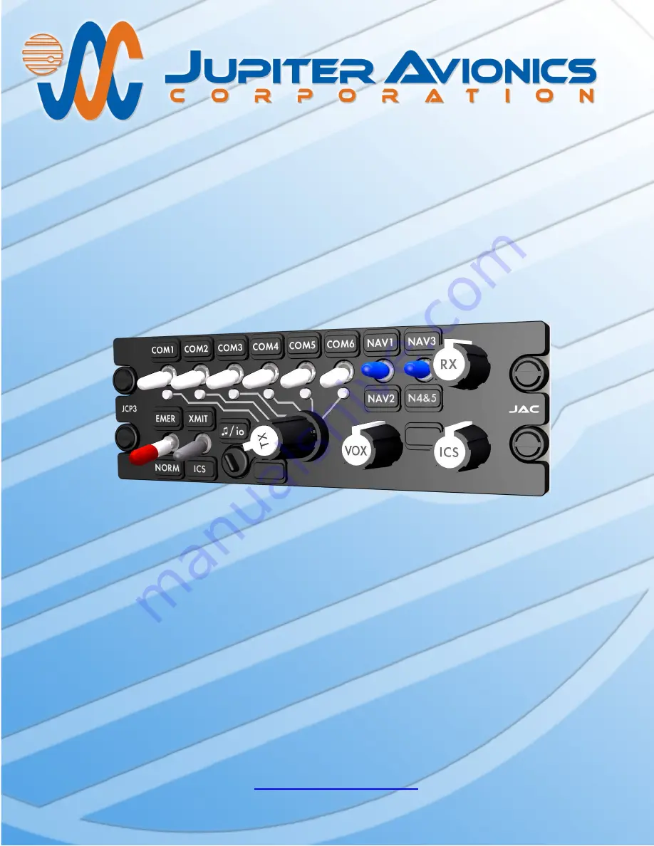
JCP3-N01
Control Panel - NVG
Installation and Operating Manual
Rev. A
Jupiter Avionics Corporation
1959 Kirschner Road
Kelowna BC
Canada V1Y 4N7
Tel: +1 778 478 2232
Toll-Free: 1 855 478 2232
www.jupiteravionics.com
Страница 1: ... N01 Control Panel NVG Installation and Operating Manual Rev A Jupiter Avionics Corporation 1959 Kirschner Road Kelowna BC Canada V1Y 4N7 Tel 1 778 478 2232 Toll Free 1 855 478 2232 www jupiteravionics com ...
Страница 2: ...istribution of this manual is strictly prohibited Except as described above no part of this manual may be reproduced copied transmitted disseminated downloaded or stored in any storage medium for any purpose without the express prior written consent of JAC RECORD OF REVISIONS Revision Rev Date Description ECR A Sep 2017 Initial release Serial number 1001 and higher 3417 Prepared MPB Checked Approv...
Страница 3: ...3 Mechanical Installation 5 2 4 4 Legend Replacement 5 2 4 5 Post Installation Checks 5 2 5 Legend Text Selection using ProCS 6 2 6 Adjustments and Configuration using ProCS 7 2 6 1 ProCS Setup 7 2 6 2 Configuring the JRAC xxx Remote Audio Controller via the JCP3 N01 7 2 7 Installation Kit 7 2 7 1 Recommended Crimp tools 7 2 8 Installation Drawings 7 SECTION 3 OPERATION 8 3 1 Introduction 8 3 2 Fr...
Страница 4: ...ansmit Operation 12 3 3 4 3 3 5 VOX Operation 12 3 3 6 ICS Operation 12 3 3 7 Multi Function XMIT ICS Switch Operation 13 Music Operation 13 3 4 Emergency Operation Mode 13 Appendix A Installation Drawings A1 A1 Introduction A1 A2 Installation Drawings A1 Appendix B Certification Documents B1 B1 Airworthiness Approval B2 B2 Instructions for Continued Airworthiness B2 ...
Страница 5: ...tification neither software nor complex electronic devices are used in the JCP3 N01 design 1 2 Features Overview The JCP3 N01 features a 15 pin D Min connector which interfaces to the JRAC 001 The JCP3 N01 input power is derived from the JRAC 001 The JCP3 N01 is NVIS Type I Class B compliant The JCP3 N01 has 1 rotary 6 position transmit selector switch The JCP3 001 has 6 transmit select annunciato...
Страница 6: ...Active low discrete TX ANNUNCIATOR 1 Active low discrete 1 3 2 Outputs Name Qty Type CONFIG DATA FROM JCP3 1 Data signal CONTROL DATA FROM JCP3 1 Data signal MODE SELECT CONFIG AUDIO 1 Multi format signal MUSIC LEFT CONFIG DATA TO REMOTE AUDIO CONTROLLER 1 Audio signal NORM MODE SELECT 1 Active low discrete 1 3 3 Bi directional Signals Name Qty Type MUSIC RIGHT CONFIG DATA FROM REMOTE AUDIO CONTRO...
Страница 7: ...x 4 95 in 125 7 mm max 0 84 lb 0 38 kg max 5052 H32 brushed aluminum with conversion coating J1 System One 15 pin D Sub male V5 locking J2 Music configuration One 4 pole 3 5mm stereo jack J3 Configuration J4 Rear stud fastener Height Behind panel depth In front of panel depth Faceplate width Behind panel width Weight Enclosure material Connectors 4 Mounting Bonding Installation kit part number One...
Страница 8: ...use misuse accident or unauthorized alteration or repairs THIS WARRANTY IS VOID IF THE PRODUCT IS NOT INSTALLED BY AN AUTHORIZED JAC DEALER If the on line warranty card is not completed the product will be warranted from the date of manufacture Contact JAC for return authorization and for any questions regarding this warranty and how it applies to your unit s JAC is the final arbiter concerning wa...
Страница 9: ...0 Chassis ground for continuity to ground less than 0 5 Ω d Confirm P1 pin 13 RESET INPUT is connected to the Remote Audio Controller P3 pin 13 RESET OUTPUT e Check all pins for shorts to ground or adjacent pins 2 4 5 2 Power on Checks Power up the aircraft s systems and confirm normal operation of all functions of the JCP3 N01 Refer to Section 3 Operation for specific operational details a Begin ...
Страница 10: ...used in the connector maps and interconnect Note If the name of a front panel switch is changed using this software the change will be incorporated in the connector maps and interconnect to give truly customized installation diagrams 2 5 2 Connector Maps This section contains connector maps and interconnects that are automatically generated to show changes to switch labels that affect the installa...
Страница 11: ...ings showing different cabling arrangements for connecting the JCP3 N01 to a computer and other equipment The front panel Music Configuration port io is protected by a urethane rubber cover which can be lifted upwards or rotated round as shown to provide access to the port io port Port cover 2 7 Installation Kit The kit required to install this unit is not included with the unit The installation k...
Страница 12: ...annunciators are removable and may be replaced with custom ordered parts For the purpose of this manual the controls will be referred to by the default legend and annunciator names as shown below The JCP3 N01 legends and annunciators are NVIS Type I Class B compliant 7 Transmit annunciator deadfront 8 Transmit selector 9 VOX threshold control 10 CALL annunciator deadfront 11 ICS volume control 1 T...
Страница 13: ...ons using this control 4 EMER NORM Mode Switch This is a red two position locking toggle switch When set to the up position the unit is Emergency mode and when set to the down position the unit is in Normal mode The legends are interchangeable to allow customization Default EMER NORM The switch is lockable to prevent accidental changing of the mode The switch must be lifted to release the lock For...
Страница 14: ... connector or cable is used damage to the unit or to any attached device may occur If in doubt contact JAC for a list of approved cables music sources and devices 7 Transmit Annunciator TX This is a deadfront annunciator that will illuminate when the JRAC 001 is transmitting The default legend is TX but it is interchangeable to allow customization 8 Transmit Selector This is a rotary six position ...
Страница 15: ...he point where no intercom audio can be heard The VOX control should be adjusted for proper operation according to the ambient noise 10 CALL Annunciator This is a customizable deadfront annunciator activated by an external switch When enabled it will illuminate when a call is received from another user s audio controller or by a remote call button within the aircraft Note Check with your installin...
Страница 16: ... select a transceiver rotate the Transmit Select Switch until it aligns with the line leading to the Transceiver Select switch legend see 1 default legends COM 1 through COM 6 The corresponding Transmit Select annunciator will illuminate When the user s TX PTT is activated the Audio System will transmit on the selected transceiver and the deadfront Transmit Annunciator 7 will illuminate TX All MIC...
Страница 17: ...transceiver when the switch is set to the up position and when set to the down position it will transmit on the intercom Alternative Operation This switch may be configured to provide a ground signal to operate other equipment 3 3 7 Music Operation Music to the phones will be muted by incoming audio ICS Receive Direct or Alert Audio or if the Audio System is transmitting When the incoming audio ha...
Страница 18: ...CP3 N01 Control Panel NVG are in this Appendix as listed below Note A fully customized set of Connector Maps and Interconnects can be created using the ProCS software Refer to the ProCS manual for further information A2 Installation Drawings DOCUMENT Rev JCP3 N01 Connector Map A JCP3 N01 Interconnect A JCP3 N01 Mechanical Installation A Reference Documents TOL CUST EXTR Legend Replacement A ...
Страница 19: ...ONTROL DATA TO JCP3 CONTROL DATA FROM JCP3 NORM MODE SELECT MUSIC LEFT CONFIG DATA TO REMOTE AUDIO CONTROLLER POWER GROUND CHASSIS GROUND CALL ANNUNCIATOR TX ANNUNCIATOR P1 15 PIN FEMALE DMIN MATING CONNECTOR 1 2 3 4 5 9 10 11 12 6 7 8 14 15 13 MUSIC CONFIG COMMON MUSIC RIGHT CONFIG DATA FROM REMOTE AUDIO CONTROLLER MODE SELECT CONFIG AUDIO RESET INPUT 5 VDC LIGHTS INPUT 28 VDC LIGHTS INPUT VIEW I...
Страница 20: ... MP3 STEREO PLAYER MATING PLUG NAMES JCP3 SIGNAL NAMES CONFIG DATA TO REMOTE AUDIO CONTROLLER CONFIG DATA FROM REMOTE AUDIO CONTROLLER MUSIC CONFIG COMMON MODE SELECT CONFIG AUDIO FRONT PANEL MUSIC LEFT FRONT PANEL MUSIC RIGHT MUSIC CONFIG COMMON FRONT PANEL MUSIC REMOTE AUDIO CONTROLLER CONFIGURATION CONNECTOR 3 POLE MALE 3 5MM STEREO P3 4 POLE MALE 3 5MM STEREO TIP TX DATA 1ST RING RX DATA 2ND R...
Страница 21: ...L SHIELDED CABLE SHOULD BE IN ACCORDANCE WITH MIL DTL 27500 REVISION H OR LATER CONNECTION TO AIRFRAME GROUND SHOULD BE MADE WITH 20 AWG WIRE LENGTH NOT TO EXCEED 3 FT 0 91 M CABLE SHIELDS AT THE CONNECTOR PINS SHOULD BE TERMINATED TO AIRFRAME GROUND USING A TAG RING P N MS27741 5 OR EQUIVALENT GROUND PIN TO ILLUMINATE ANNUNCIATOR ON FACEPLATE MOMENTARILY GROUND PIN TO RESET CONTROL PANEL ONLY CON...
Страница 22: ...IG COMMON 8 POWER INPUT 1 POWER GROUND 9 CALL ANNUNCIATOR 11 5 VDC LIGHTS 14 28 VDC LIGHTS 15 FROM REMOTE AUDIO CONTROLLER TO REMOTE AUDIO CONTROLLER TX ANNUNCIATOR 12 CONTROL DATA FROM JRAC CONTROL DATA TO JRAC 2 3 NORM MODE SELECT 4 CONTROL CONNECTOR J3 P3 15 PIN MALE DMIN MATING CONNECTOR CHASSIS GROUND 10 RESET OUTPUT 13 CONTROL PANEL MUSIC LEFT 5 JRAC 001 CONTROL PANEL MUSIC RIGHT 6 MODE SELE...
Страница 23: ...99 001 CONFIGURATION CABLE P3 4 POLE MALE 3 5MM STEREO MATING CONNECTOR JCP3 CONFIGURATION VIA JCP3 CONFIGURATION CONNECTOR J3 CONFIG DATA TO JCP3 CONFIG DATA FROM JCP3 GROUND MODE SELECT CONFIG DATA TO JCP3 CONFIG DATA FROM JCP3 GROUND 3RD RING TIP 1ST RING 2ND RING MODE SELECT LEFT MUSIC STEREO PLAYER RIGHT MUSIC GROUND P2 3 POLE MALE 3 5MM STEREO MATING CONNECTOR OPTION STEREO PLAYER INPUT VIA ...
Страница 24: ...P3 N01 Mechanical Installation Rev A SLDDRW DOC NO 1 1 SHEET JCP3 N01 PART NO TITLE CONFIDENTIAL PROPRIETARY TO JUPITER AVIONICS CORP APPROVED CHECKED TAT PREPARED N A N A MATERIAL FINISH NCAGE CODE L00N3 DRAWING NOT TO SCALE UNLESS OTHERWISE SPECIFIED DIMENSIONS ARE IN INCHES ANGLES ARE IN DEGREES TOLERANCES 1 DEC PLACE 0 1 2 DEC PLACE 0 01 3 DEC PLACE 0 005 ANGLES Control Panel NVG qu ii J2 5 75...
Страница 25: ...only minimal changes The internal circuitry ensures that although the legends are individually illuminated the illumination is consistent and uniform throughout all legends and never needs to be balanced This means that if it is a requirement to change the labelling due to damage or for a different project there is no need for costly and time consuming illumination checks Caution Take care not to ...
Страница 26: ...Rev A Page B1 JCP3 N01 Control Panel NVG Installation and Operating Manual Appendix B Certification Documents ...
Страница 27: ...st weights and balance amended Compass compensation checked and found to conform to applicable regulations B2 Instructions for Continued Airworthiness Maintenance of the JCP3 N01 Control Panel NVG is on condition only Refer to the JCP3 N01 Maintenance Manual Periodic maintenance of the JCP3 N01 is not required The following sample Instructions for Continued Airworthiness ICA provides assistance in...
Страница 28: ...he JCP3 N01 Installation and Operating Manual If the unit is removed and reinstalled a functional check of the equipment should be conducted 8 Diagrams Refer to Appendix A of this manual the JCP3 N01 Installation and Operating Manual for installation drawings and interconnect examples 9 Special Inspection Requirements N A 10 Application of Protective Treatments N A 11 Data Relative to Structural F...
Страница 29: ...1 Equipment tested to Category C4 45 C Operating Low Temperature 4 5 2 Equipment tested to Category C4 45 C Ground Survival High Temperature 4 5 3 Equipment tested to Category C4 85 C Short Time Operating High Temperature 4 5 3 Equipment tested to Category C4 70 C Operating High Temperature 4 5 4 Equipment tested to Category C4 70 C In Flight Loss of Cooling 4 5 5 Equipment identified as Category ...
Страница 30: ...ler tested to Category Z 28 Vdc equipment JRAC 001 Remote Audio Controller tested to Category B 14 Vdc equipment Induced Signal Susceptibility Magnetic Fields into Equipment Magnetic Fields into Interconnect Electric Fields into Interconnect Voltage Spikes into Interconnect 19 0 19 3 1 19 3 3 19 3 4 19 3 5 Equipment tested to Category ZCX 20 A at 400Hz 30 A m at 400Hz 1800 V m at 400Hz 3 0 m Radio...
Страница 31: ...Jupiter Avionics Corp document JCP3 001 Test Report Qualification Final Rev A 1 During exposure to vibration test conditions all critical resonances changed frequency less than 1 5 2 The JCP3 001 Control Panel was operating a JRAC 001 Remote Audio Controller during the power input voltage spike and audio frequency conducted susceptibility tests During these tests the JRAC 001 Remote Audio Controll...