Jupiter Avionics JA95-N60 Скачать руководство пользователя страница 1

Rev B 

Page i 

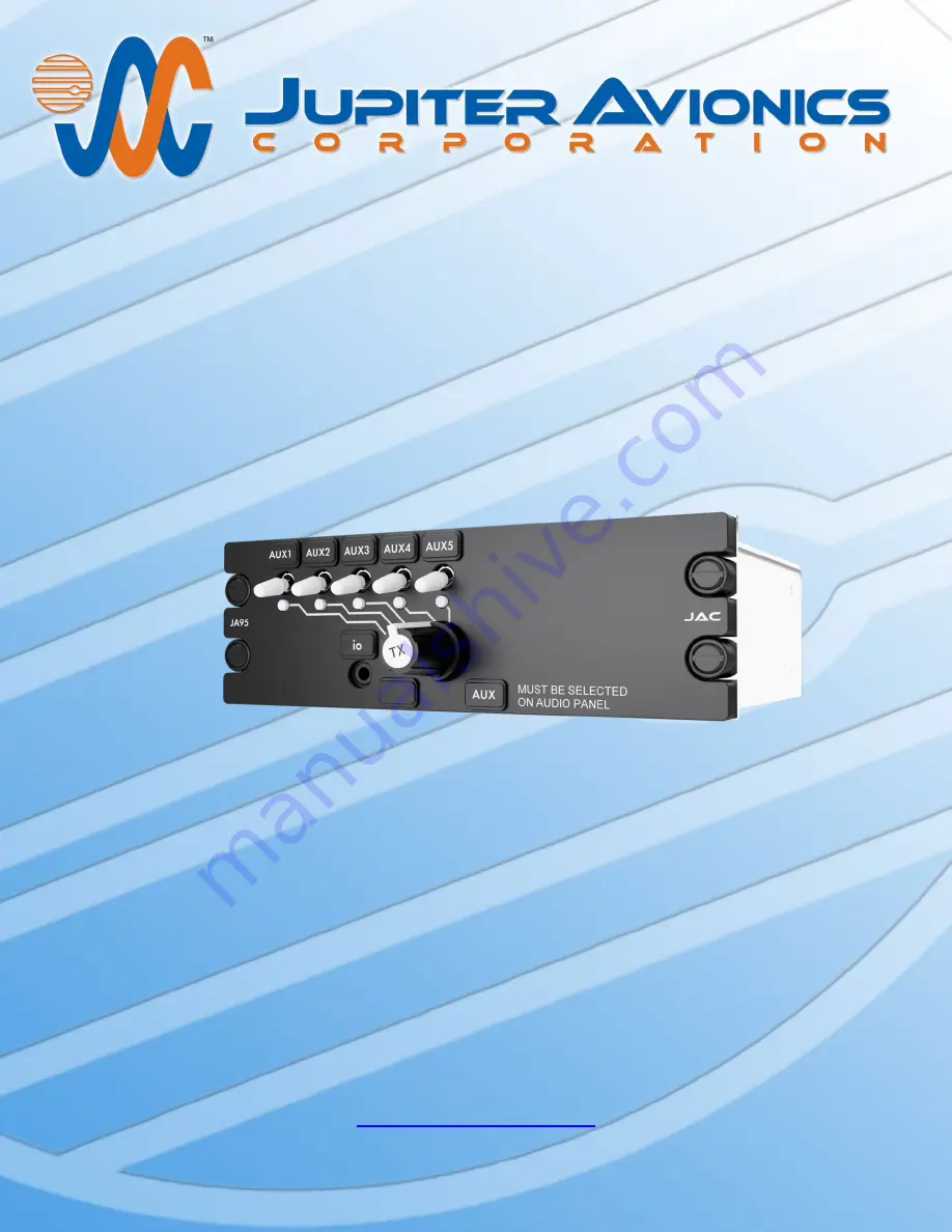
JA95-N60 Audio Controller  

Five Transceiver - Expander - NVG 

Installation and Operating Manual 

Rev A 

Jupiter Avionics Corporation 

1959 Kirschner Road 

Kelowna BC 

Canada   V1Y 4N7    

Tel: +1 778 478 2232 

Toll-Free: 1 855 478 2232 

www.jupiteravionics.com

Содержание JA95-N60

Страница 1: ...io Controller Five Transceiver Expander NVG Installation and Operating Manual Rev A Jupiter Avionics Corporation 1959 Kirschner Road Kelowna BC Canada V1Y 4N7 Tel 1 778 478 2232 Toll Free 1 855 478 2232 www jupiteravionics com ...

Страница 2: ... commercial distribution of this manual is strictly prohibited Except as described above no part of this manual may be reproduced copied transmitted disseminated downloaded or stored in any storage medium for any purpose without the express prior written consent of JAC RECORD OF REVISIONS Revision Rev Date Description ECR A Jun 2022 Initial release Serial number 1001 and higher 8614 Prepared DGB M...

Страница 3: ...t 6 2 4 5 Post Installation Checks 6 2 5 Adjustments and Configuration using ProCS 6 2 5 1 Configuration Cabling Requirements 7 2 5 2 ProCS Setup 7 2 5 3 Configurable Settings 7 2 5 4 Other Configuration Features 9 2 6 Installation Kit 9 2 6 1 Recommended Crimp Tools 9 2 7 Installation Drawings 10 2 7 1 Generation of Custom Drawings 10 SECTION 3 OPERATION 11 3 1 Introduction 11 3 2 System Diagram ...

Страница 4: ...t levels are adjustable and several audio paths are selectable A configuration connector is provided on the faceplate of the JA95 N60 for configuration of audio levels and routing The JA95 N60 has two modes of operation Normal Mode and Emergency Mode The JA95 N60 supports up to five transceivers each selectable from a rotary switch The JA95 N60 allows transmit access for one audio panel The JA95 N...

Страница 5: ... rated output in emergency mode or with power input 6 Vdc 2 10 Vrms 10 Microphone rated output 250 mVrms 10 Audio Frequency Response Audio output audio frequency response 3dB from 300 to 6000 Hz Spurious Responses Audio output spurious response attenuation 50 dB Distortion Characteristics Audio output distortion at rated power 10 Input Impedance Microphone input Impedance 150 Ω 10 Receive Audio in...

Страница 6: ...gnals have internal pull up resistor Active low control output active output 2 Vdc Active low control output active signal sinks 1 Adc 1 4 1 4 Lights Input LIGHTS INPUT ranges 0 to 28 0 to 14 and 0 to 5 Vdc LIGHTS INPUT current 10 mA max 1 4 2 Mechanical Specifications Height 1 875 in 47 6 mm max Behind panel depth 5 48 in 139 mm max Faceplate width 5 75 in 146 mm max Behind panel width 5 00 in 12...

Страница 7: ...rials The JA95 N60 complies with the requirements of RTCA DO 160G Sec 26 3 3 Flammability through equivalent flammability testing of materials and the Small Parts Exemption 1 4 6 Environmental Specifications The JA95 N60 Audio Controller Five Transceiver Expander NVG has been qualified to the environmental conditions listed below Environmental categories for which TSO compliance has been demonstra...

Страница 8: ...UTHORIZED JAC DEALER If the on line warranty card is not completed the product will be warranted from the date of manufacture Contact JAC for return authorization and for any questions regarding this warranty and how it applies to your unit s JAC is the final arbiter concerning warranty issues 2 4 Installation Procedures WARNING Loud noise can cause hearing damage Set the headset volume to minimum...

Страница 9: ...ights buss voltage b Check P2 pin 17 for 28 Vdc or 14 Vdc relative to ground c Check P2 pin 34 for continuity to ground less than 0 5 Ω d Check all pins for shorts to ground or adjacent pins 2 4 5 2 Configuration Ensure that the JA95 N60 contains the correct configuration settings This may be done at the factory on the maintenance bench or in the aircraft before the power on checks are performed R...

Страница 10: ...ty Description JA95 N60 1 USB A to RS232 9 Pin Cable CAB USB 0002 1 Configuration Cable JA99 001 2 5 2 ProCS Setup The ProCS JA95 N60 menu item ProCS Setup provides a drawing showing the cabling arrangement for connecting the JA95 N60 to a computer running the ProCS 2 5 3 Configurable Settings A standard unit is shipped from the factory with all internal adjustments configured to the default level...

Страница 11: ...vels The Transceiver MIC output signals can be adjusted from 0 010 to 1 000 Vrms Default 250 mVrms The Radios window is used to define the radios for the transceivers The receive level of each of the RX inputs can be adjusted from 1 to 10 Vrms Default 7 75 Vrms When the Transmit Timeout check box is checked the transmit time out is enabled Default not checked ...

Страница 12: ...95 consists of the following Quantity Description JAC Part 2 TAG ring CON 5500 0625 1 D Sub 37 pin connector hood and 37 crimp pins CON 3420 0037 1 D Sub 50 pin connector hood and 50 crimp pins CON 3420 0050 2 Heat Shrink Tubing WIR HTSK 1000 2 6 1 Recommended Crimp Tools Standard D Sub Crimp Tool Chart Tool Type Hand crimping tool Positioner Insertion extractor tool POSITRONIC 9507 0 0 0 9502 5 0...

Страница 13: ... A of this manual 2 7 1 Generation of Custom Drawings The interconnects and connector maps in Appendix A of this manual are generic drawings based on the standard version of the JA95 N60 However if a unit has been configured using JAC s ProCS software to change switch legends or lighting voltages the software can be used to generate fully customized interconnects and connector maps for use by the ...

Страница 14: ...sceiver Expander NVG is a compact lightweight panel that allows connection of up to 4 additional radios to the aircraft audio system The JA95 N60 is compatible with the transceiver connections of any of Jupiter s JA9x series of audio controllers as well as any civil aviation audio controller The text on the JA95 N60 legend shown here as AUX should be selected to match the text on the main panel le...

Страница 15: ...r and legend 3 Transmit annunciator deadfront 4 Transmit selector 5 AUX Legend 1 Transceiver Switches These are five white two position toggle switches When a switch is set to the up position audio from the associated transceiver is routed to the phones The legends above the switches are interchangeable to allow customization Default AUX1 AUX2 AUX3 AUX4 AUX5 2 Configuration Connector io This conne...

Страница 16: ...gend This is a customizable legend that is intended to remind the operator which transceiver on the main audio panel must be selected to allow transmission on the JA95 N60 Expander NVG Panel The default legend is AUX but it is interchangeable to allow customization to match the legend on the main audio panel 3 4 Normal Operation Mode Note Numbers in parentheses refer to the front panel controls sh...

Страница 17: ...rresponding Transmit Select annunciator will illuminate When the TX PTT input is activated the unit will transmit on the selected transceiver and the deadfront Transmit Annunciator 3 will illuminate TX All MIC and sidetone audio will be routed to the RX OUTPUT 3 5 Emergency Operation Mode Emergency mode is entered automatically if power to the unit is lost 3 5 1 Auto Emergency Mode If the unit is ...

Страница 18: ...troller Five Transceiver Expander NVG are in this Appendix as listed below Note A fully customized set of Connector Maps and Interconnects can be created using the ProCS software Refer to the ProCS manual for further information A2 Installation Drawings DOCUMENT Rev JA95 N60 Connector Map A JA95 N60 Interconnect A JA95 N60 Mechanical Installation A JA95 N60 Equipment Block Diagram A Reference Docu...

Страница 19: ...6 17 20 21 22 23 24 25 26 27 28 29 30 31 32 33 34 35 18 19 36 37 SPARE 1 AUX 1 RX HI AUX 2 RX HI AUX 3 RX HI AUX 4 RX HI AUX 5 RX HI SPARE 2 SPARE 3 SPARE 4 SPARE 5 SPARE 6 SPARE 7 SPARE 8 SPARE 9 SPARE 10 SPARE 11 SPARE 12 RX OUTPUT HI LIGHTS INPUT SPARE 13 AUX 1 RX LO AUX 2 RX LO AUX 3 RX LO AUX 4 RX LO AUX 5 RX LO SPARE 14 SPARE 15 SPARE 16 SPARE 17 SPARE 18 SPARE 19 SPARE 20 SPARE 21 SPARE 22 ...

Страница 20: ... 47 48 49 50 AUX 1 PTT AUX 1 MIC HI AUX 1 MIC LO AUX 2 MIC HI AUX 2 MIC LO AUX 3 MIC HI AUX 3 MIC LO AUX 4 MIC HI AUX 4 MIC LO AUX 5 MIC HI AUX 5 MIC LO SPARE 11 SPARE 12 TX MIC HI TX MIC LO SPARE 13 SPARE 14 SPARE 15 SPARE 16 SPARE 17 SPARE 18 SPARE 19 SPARE 20 SPARE 21 SPARE 22 SPARE 23 SPARE 24 SPARE 25 SPARE 26 SPARE 29 SPARE 30 AUX 2 PTT AUX 3 PTT AUX 4 PTT AUX 5 PTT SPARE 1 SPARE 2 SPARE 4 S...

Страница 21: ...e Transceiver Expander NVG P3 Connector Map JA95 N60 3 3 JA95 N60 Connector Map Rev A dwg TAT P3 4 POLE MALE 3 5MM STEREO TIP TX DATA 1ST RING RX DATA 2ND RING GROUND 3RD RING CONFIG AUDIO ACCEPTS THE FOLLOWING PLUG FORMATS JA99 CONFIGURATION CABLE MATING PLUG NAMES JA95 SIGNAL NAMES CONFIG DATA TO JA95 CONFIG DATA FROM JA95 GROUND MODE SELECT CONFIG AUDIO FRONT PANEL MUSIC CONFIGURATION CONNECTOR...

Страница 22: ...TO EXCEED 3 FT 0 9 M CABLE SHIELDS AT THE JA95 N60 CONNECTOR PINS SHOULD BE TERMINATED TO AIRFRAME GROUND USING A TAG RING P N MS27741 5 OR EQUIVALENT ONLY 28 VDC OR 14 VDC OR 5 VDC LIGHTS INPUT VOLTAGE MAY BE APPLIED AT ONE TIME 2 1 3 4 CONNECTOR PIN LEGENDS LEGEND SPARE INTERNAL CIRCUITS MAY EXIST AND MAY BE ACTIVATED FOR FUTURE USE NO EXTERNAL WIRE CONNECTION JUPITER AVIONICS TEMPLATE AUTOCAD P...

Страница 23: ...0 SPARE 22 15 34 SPARE 11 SPARE 23 16 35 SPARE 12 SPARE 24 17 36 RX OUTPUT HI RX OUTPUT LO RX LO AUX INPUT 18 37 LIGHTS INPUT 28 VDC LIGHTS 19 JA95 N60 J1 P1 37 PIN FEMALE DMIN MATING CONNECTOR 2 3 2 SPARE 1 SPARE 13 1 20 5 14 VDC LIGHTS 5 5 VDC LIGHTS 5 AUDIO CONTROLLER JUPITER AVIONICS TEMPLATE AUTOCAD PORTRAIT SIZEA REV B DWT TITLE APPROVED PREPARED CHECKED L00N3 NCAGE CODE PART NO SHEET DOC NO...

Страница 24: ...PARE 17 SPARE 27 30 47 SPARE 13 SPARE 23 26 43 SPARE 18 SPARE 28 31 48 SPARE 14 SPARE 24 27 44 SPARE 19 SPARE 29 32 49 SPARE 15 SPARE 25 28 45 SPARE 20 SPARE 30 33 50 SPARE 16 SPARE 26 29 46 SPARE 8 SPARE 9 14 15 SPARE 1 6 SPARE 5 11 SPARE 6 12 SPARE 7 13 SPARE 10 16 POWER INPUT 28 VDC POWER 17 POWER GROUND AIRFRAME GROUND 34 1A 22 AWG 22 AWG 2 3 2 2 KEY AUDIO CONTROLLER JUPITER AVIONICS TEMPLATE ...

Страница 25: ...FROM JA95 GROUND MODE SELECT CONFIG AUDIO CONFIG DATA TO JA95 CONFIG DATA FROM JA95 GROUND 3RD RING TIP 1ST RING 2ND RING MODE SELECT CONFIG AUDIO JUPITER AVIONICS TEMPLATE AUTOCAD PORTRAIT SIZEA REV B DWT TITLE APPROVED PREPARED CHECKED L00N3 NCAGE CODE PART NO SHEET DOC NO CONFIDENTIAL PROPRIETARY TO JUPITER AVIONICS CORP Audio Controller Five Transceiver Expander NVG Interconnect Options JA95 N...

Страница 26: ...iver Expander NVG FINISH SHEET JA95 N60 PART NO TITLE 0 5 DEG UNLESS OTHERWISE SPECIFIED DIMENSIONS ARE IN INCHES ANGLES ARE IN DEGREES TOLERANCES 1 DEC PLACE 0 1 2 DEC PLACE 0 01 3 DEC PLACE 0 005 ANGLES CONFIDENTIAL PROPRIETARY DRAWING NOT TO SCALE 0 03in 0 8mm CENTER OF GRAVITY WEIGHT 1 64 lbs 0 74 kg MAX J3 5 75in MAX 146mm MAX 1 875in MAX 47 63mm MAX 5 48in MAX 139mm MAX 127mm MAX 5 00in MAX ...

Страница 27: ...RY TO JUPITER AVIONICS CORP Audio Controller Five Transceiver Expander NVG Equipment Block Diagram JA95 N60 1 1 JA95 N60 Equipment Block Diagram Rev A dwg TAT AUX 1 AUX 2 AUX 3 AUX 4 AUX 5 MAIN TX AUX 1 5 MIC AUX 1 5 PTT AUX 1 5 RX TX MIC TX PTT RX OUTPUT JA95 N60 AUDIO PANEL EXPANSION AUDIO PANEL EXPANSION TRANSCEIVERS JAC AH 06 07 22 JAC KDV 06 07 22 ...

Страница 28: ...only minimal changes The internal circuitry ensures that although the legends are individually illuminated the illumination is consistent and uniform throughout all legends and never needs to be balanced This means that if it is a requirement to change the labelling due to damage or for a different project there is no need for costly and time consuming illumination checks Caution Take care not to ...

Страница 29: ...Rev A Page B1 JA95 N60 Audio Controller Five Transceiver Expander NVG Installation and Operating Manual Appendix B Certification Documents ...

Страница 30: ...inal audio panel The net electrical load is unchanged Aircraft equipment list weights and balance amended Compass compensation checked and found to conform to applicable regulations B2 Instructions for Continued Airworthiness Maintenance of the JA95 N60 Audio Controller Five Transceiver Expander NVG is on condition only Periodic maintenance of the JA95 N60 is not required The following sample Inst...

Страница 31: ... Section 2 of this manual the JA95 N60 Installation and Operating Manual If the unit is removed and reinstalled a functional check of the equipment should be conducted 8 Diagrams Refer to Appendix A of this manual the JA95 N60 Installation and Operating Manual for installation drawings and interconnect examples 9 Special Inspection Requirements N A 10 Application of Protective Treatments N A 11 Da...

Страница 32: ...00 ft Decompression 4 6 2 Equipment tested to Category A1 8 000 to 50 000 ft Overpressure 4 6 3 Equipment tested to Category A1 15 000 ft Temperature Variation 5 0 Equipment tested to Category B 5 C min Humidity 6 0 Equipment tested to Category A 48 hours Nomenclature Audio Controller Five Transceiver Expander NVG Type Model Part No JA95 N60 TSO No CAN TSO C139 TSO C139 Manufacturer s Build Config...

Страница 33: ...ory X no test performed Fluids Susceptibility 11 0 Equipment identified as Category X no test performed Sand and Dust 12 0 Equipment identified as Category X no test performed Fungus 13 0 Equipment identified as Category X no test performed Salt Fog Test 14 0 Equipment identified as Category X no test performed Magnetic Effect 15 0 Equipment tested to Category Z 0 D 0 3 m Power Input DC Equipment ...

Страница 34: ...d Electrostatic Discharge 25 0 Equipment identified as Category X no test performed Fire Flammability 26 0 Equipment identified as Category X no test performed Other Tests N A N A REMARKS 1 This product is a derivative of the JA95 001 All tests were performed on a JA95 001 and JA95 060 A similarity analysis between the two products is detailed in the Jupiter Avionics Corp document JA95 N60 CAN TSO...

Отзывы: