


9
proceed as follows:
a. Request an active carbon filter suitable
for this model from your supplier.
b. Remove the metal grease filters pulling
upwards and extract outwards (Fig. 3).
c. Fit the carbon filter on its proper housing,
first on the upper hooks then, using two
locking keys D, on the lower hooks (Fig.
4).
d. The deflector E (Fig. 5) must be fitted on
the hole B fixing it with the special screws
provided.
e. Refit the metalgrease filters.
The deflector conveys the air frontwards
avoiding to dirty the rear wall.
Attention
When installed, the hood must be not less
than 65 cm. above electric burners or 75
cm. above gas or mixed-fuel burners.
Warning!
— The hood cannot be connected to flues of
other appliances that run on energy
sources other than electricity.
— When the hood is used at the same time
of other appliances that run on energy
sources other than electricity, provision
must be made for an adequate supply of
air.
— No food must be cooked flambé
underneath the hood.
The use of an unprotected flame is
dangerous for the filters and could cause
fires.
Therefore, never use an open flame under
the hood. When frying foods, never leave
the pan alone because the cooking oil
could flare up.
— Please, keep to the provisions of official
directives regarding the question of fume
discharge.
— The manufacturers refuse to accept any
responsibility for damage to the hood or
its catching on fire because of failure to
observe the above instructions.
GB
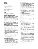
View of the hood
1) Flap
2) Grease filters
3) Cooking surface lighting
4) Motor speed selector
5) Light switch
Use
Two systems are available:
External exhausting system
Vapour is expelled by means of an exhaust
tube which is fixed to the coupling ring.
Diameter of the exhausting pipe must
be equal to that of the connection ring.
The hood has two exhaust holes, one at
the back and one at the top.
The hood may be used with the top
exhaust hole (Ø120mm coupling ring
already mounted - Fig. 1)
According to your installation the pipe can be
directed either towards the ceiling or towards
the walls (Fig. 2).
Use the rear exhaust hole if air may be
pushed to the outside by means of a hole in
the back wall (Fig. 1a):
1. Remove the coupling ring (remove the
fixing screw) from the top hole.
2. Remove the 2 screws which fix the rear
plug.
3. Re-fit the 2 screws.
4. Fit the deflector and fix with 1 screw.
5. Insert the coupling ring into the rear
exhaust hole + fixing screw.
Internal recycle system
— The air is purified through an active carbon
filter and returned to the room.
— The use of an active carbon filter is
necessary when an exhaust pipe to the
exterior is not available, or when it is not
possible to install this type of pipe.
In the case of the internal recycle version
Содержание JDS 3530
Страница 2: ...2 Fig 1 1 3 5 4 O 1 2 3 O I 2 Fig 1a Fig 2 Fig 3 ...
Страница 3: ...3 Fig 9 Fig 5 Fig 4 Fig 10 Fig 6 Fig 7 F G 0 90 0 54 54 100 F L I J M N H Fig 8 3 O P E B N1U N3U D D ...
Страница 4: ...4 C1 C2 B1 B2 R R Fig 13 Fig 14 Q Fig 11 B B2 B1 C C2 C1 Fig 12 N2I N2I ...
Страница 12: ...LI08SA ELECTROLUX ZANUSSIHAUSGERÄTEGMBH Rennbahnstraße72 74 D 60528Frankfurt ...


