background image

Connect Power to SSR120

Ensure that you have a power cord appropriate for your geographical location.

To connect power to the appliance:

1. Locate the power cord shipped with the appliance.

WARNING:

Ensure that the power cord does not drape where people can trip on

it or block access to the appliance components.

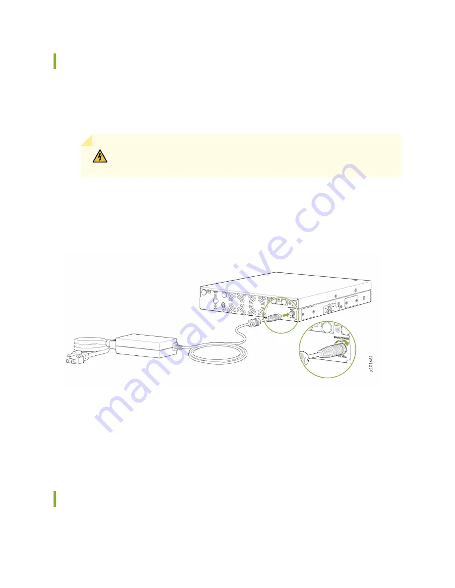
2. Plug the power cord barrel connector into the +12 VDC input on the appliance and tighten the lock

ring. See

Figure 15 on page 37

.

Figure 15: Connecting the SSR120 to the Power Supply

3. If the AC power source outlet has a power switch, set it to the OFF (0) position.

4. Insert the power cord plug into an AC power source outlet.

5. If the AC power source outlet has a power switch, set it to the ON (|) position.

Power Off the SSR120

You can power off the SSR120 in one of the following ways:

37

Содержание SSR120

Страница 1: ...SSR120 Hardware Guide Published 2022 01 17 ...

Страница 2: ... Copyright 2022 Juniper Networks Inc All rights reserved The information in this document is current as of the date on the title page YEAR 2000 NOTICE Juniper Networks hardware and software products are Year 2000 compliant Junos OS has no known time related limitations through the year 2038 However the NTP application is known to have some difficulty in the year 2036 END USER LICENSE AGREEMENT The...

Страница 3: ...w 15 Antennas 16 Firmware Upgrade Support 17 Site Planning Preparation and Specifications 2 Site Preparation Checklist for SSR120 19 SSR120 Site Guidelines and Requirements 20 General Site Installation Guidelines 21 Site Electrical Wiring Guidelines 21 Chassis Physical Specifications for SSR120 22 Environmental Requirements and Specifications for SSR120 22 Clearance Requirements for Hardware Maint...

Страница 4: ...ting the SIM Card 34 Connect SSR120 to Power 35 Connect Earth Ground to SSR120 35 Connect Power to SSR120 37 Power Off the SSR120 37 Connect SSR120 to External Devices 38 Connect SSR120 to a Management Console 39 Configuring SSR Software on the SSR120 40 Configure the SSR120 Appliance from the SSR Conductor 40 QuickStart From the OTP ISO 43 Contacting Customer Support and Returning the Chassis or ...

Страница 5: ...s 1M Laser Product Warning 68 Class 1M Laser Radiation Warning 68 Class 1 Laser Product Warning 69 Class 1 LED Product Warning 70 Laser Beam Warning 71 Unterminated Fiber Optic Cable Warning 72 Chassis and Component Lifting Guidelines 74 Radiation from Open Port Apertures Warning 75 Maintenance and Operational Safety Guidelines and Warnings 76 Battery Handling Warning 77 Jewelry Removal Warning 78...

Страница 6: ...AC Power Electrical Safety Guidelines 85 SSR120 Agency Approvals 86 FCC Declarations 87 Lithium Battery Declaration 87 vi ...

Страница 7: ...1 CHAPTER Overview SSR120 Appliance Overview 8 SSR120 Chassis 10 LTE Support on SSR120 Appliances 15 ...

Страница 8: ...he SSR120 features four 1 GbE ports two 1 GbE RJ 45 SFP combo ports 8 GB of memory and a 120 GB enterprise grade solid state drive SSD for storage The SSR120 runs the FIPS 140 2 Level 1 compliant Session Smart Router SSR software which provides secure and resilient WAN connectivity The SSR120 appliance is available in models with or without LTE support Benefits of SSR120 The SSR120 provides these ...

Страница 9: ...y capabilities with no loss ensure that application traffic is optimized across multiple paths and delivered despite failures Wireless WAN support In addition to Ethernet connections Wireless WAN support through the LTE module provides more flexibility in deployments SSR120 Models The SSR120 is available in three different models with or without LTE support NOTE To use the SSR120 appliance you mus...

Страница 10: ...New Zealand Yes integrated LTE modem for North America and Europe No LTE support SSR120 Chassis IN THIS SECTION Front Panel of an SSR120 10 Rear Panel of an SSR120 12 Chassis Status LEDs 12 Network Port LEDs 13 SSR120 Power System 14 Cooling System 14 Front Panel of an SSR120 Figure 1 on page 11 shows the front panel of an SSR120 10 ...

Страница 11: ...igure 2 Front Panel Components of SSR120 AA and SSR120 AE 5 1 1 GbE RJ 45 SFP Combo Ports Antenna connectors 6 2 USB 3 0 port Power button 7 3 Reset button Console Port 8 4 Chassis LEDs 1 GbE Ethernet Ports The SSR120 supports two 1 GbE RJ 45 SFP combo ports for WAN connectivity You can connect either an SFP fiber or RJ 45 copper cable on the 1 GbE RJ 45 SFP combo port The SSR120 automatically det...

Страница 12: ...sabled media is powered up and both media tries to establish the link again Rear Panel of an SSR120 Figure 3 on page 12 shows the rear panel of an SSR120 Figure 3 SSR120 Rear Panel 3 1 Power input Ground terminal 2 Fan NOTE The SSR120 does not support PoE power input Chassis Status LEDs The SSR120 has three LEDs on the front panel to indicate the status Figure 4 Chassis Status LEDs in an SSR120 12...

Страница 13: ...e OS boot process is complete LED 1 On Amber LED 2 Off Unlit LED 3 On Blue Device is powered off by the OS Network Port LEDs Each network port has two LEDs to indicate the link activity and status of the port Figure 5 Network Port LEDs on SSR120 3 1 Link RJ 45 SFP combo port Link Ethernet port 4 2 Activity RJ 45 SFP combo port Activity Ethernet port Table 3 on page 14 describes the Link and Activi...

Страница 14: ... supply adapter Table 4 Specifications for the SSR120 Power Adapter Maximum Power Consumption Power Adapter Output DC Power Adapter Input AC Model 32 5 W 12V DC 5 A 100 240V AC 50 60 Hz 2 A SSR120 32 5 W 12V DC 5 A 100 240V AC 50 60 Hz 2 A SSR120 AA 32 5 W 12V DC 5 A 100 240V AC 50 60 Hz 2 A SSR120 AE Cooling System The cooling system of the SSR120 consists of a single fan The fan controller on th...

Страница 15: ...as 16 Firmware Upgrade Support 17 Overview The SSR120 portfolio consists of models with or without LTE support The LTE support is provided through the in built LTE module that operates on both 3G and 4G networks The SSR120 supports only a single SIM card Table 5 on page 16 provides a summary of the models that support LTE 15 ...

Страница 16: ...8 9 and 19 Asia Pacific Australia New Zealand 4G LTE Cat 6 3G HSPA UMTS SSR120 AA Antennas The LTE module supports two multi band swivel mount dipole antennas which can be rotated 90 You can rotate the antennas and select the angle at which the signal strength is high Table 6 on page 16 lists the specifications for the antenna Table 6 Antenna Specifications for the LTE Module Value Specification A...

Страница 17: ...z 2 5 dBi 1950 MHz 2 2 dBi 2250 MHz 2 6 dBi 2450 MHz 2 7 dBi 3700 MHz 3 5 dBi 5500 MHz Peak Gain 50 Ohms Impedance 252 mm x 35 mm x 13 mm Dimensions L x W X H Firmware Upgrade Support The LTE module supports over the air OTA firmware upgrade which enables automatic and timely upgrade of modem firmware when new firmware versions are available 17 ...

Страница 18: ...2 CHAPTER Site Planning Preparation and Specifications Site Preparation Checklist for SSR120 19 SSR120 Site Guidelines and Requirements 20 Cable Specifications and Pinouts for SSR120 25 ...

Страница 19: ...wer Measure the distance between external power sources and the installation site Locate sites for connection of system grounding Calculate the power consumption and requirements Rack Rack Requirements for SSR120 on page 24 Verify that your rack or cabinet meets the minimum requirements for the installation of the appliance Plan rack location including required space clearances Secure the rack or ...

Страница 20: ...llowed for each cable Choose the length of cable based on the distance between the hardware components being connected Plan the cable routing and management SSR120 Site Guidelines and Requirements IN THIS SECTION General Site Installation Guidelines 21 Site Electrical Wiring Guidelines 21 Chassis Physical Specifications for SSR120 22 Environmental Requirements and Specifications for SSR120 22 Clea...

Страница 21: ...trical Wiring Guidelines Table 8 on page 21 describes the factors you must consider while planning the electrical wiring at your site WARNING You must provide a properly grounded and shielded environment and use electrical surge suppression devices Avertissement Vous devez établir un environnement protégé et convenablement mis à la terre et utiliser des dispositifs de parasurtension Table 8 Site E...

Страница 22: ...and receivers in the device Electrical hazards as a result of power surges conducted over the lines into the equipment Electromagnetic compatibility Chassis Physical Specifications for SSR120 Table 9 on page 22 summarizes the physical specifications of SSR120 Table 9 Physical Specifications of SSR120 Weight Height Width Depth Model 3 68 lb 1 69 kg 1 73 in 4 4 cm 8 74 in 22 2 cm 9 49 in 24 1 cm SSR...

Страница 23: ...en planning the site for installing an SSR120 you must allow sufficient clearance around the installed chassis For the operating temperature of the SSR120 to be optimal the airflow around the chassis must be unrestricted For service personnel to remove and install hardware components and to accommodate the interface and power cable bend radius there must be adequate space at the front and rear of ...

Страница 24: ...low at least 6 in 15 2 cm of clearance between the front and back of the chassis and adjacent equipment or walls Ensure that the desktop or other level surface on which the appliance is installed is stable and securely supported Rack Requirements for SSR120 You can mount the SSR120 on two post racks You must order the rack mounting kit part number SSR100 RMK separately Table 11 on page 25 provides...

Страница 25: ...he standards for a 19 in rack as defined in Cabinets Racks Panels and Associated Equipment document number EIA 310 D published by the Electronics Industry Association Ensure that the spacing of rails and adjacent racks allows for proper clearance around the appliance and rack Ensure that the rack rails are spaced widely enough to accommodate the chassis external dimensions The outer edges of the f...

Страница 26: ...nector An RJ 45 cable and RJ 45 to DB 9 adapter are supplied with the appliance Table 12 Console Port Connector Pinouts Description Signal Pin Request to send RTS Output 1 Data terminal ready DTR Output 2 Transmit data TxD Output 3 Ground Ground 4 Ground Ground 5 Receive data RxD Input 6 Data set ready DSR Input 7 Clear to send CTS Input 8 Pluggable Transceivers Supported on SSR120 The 1 GbE RJ 45...

Страница 27: ...3 CHAPTER Initial Installation and Configuration Unpack and Mount an SSR120 28 Connect SSR120 to Power 35 Connect SSR120 to External Devices 38 Configuring SSR Software on the SSR120 40 ...

Страница 28: ...The carton also contains an accessory box and quick start instructions NOTE The SSR120 is maximally protected inside the cardboard carton Do not unpack it until you are ready to begin installation To unpack the SSR120 1 Move the cardboard carton to a staging area as close to the installation site as possible where you have enough room to remove the components from the chassis 2 Position the cardbo...

Страница 29: ... or Canada by telephone at 1 888 314 5822 For international dial or direct dial options in countries without toll free numbers see https www juniper net support requesting support html Table 13 Parts List for a Fully Configured SSR120 Quantity Component 1 SSR120 Chassis 1 DB 9 to RJ 45 adapter straight through cable 1 C13 power cord appropriate for your geographical location 1 AC DC power adapter ...

Страница 30: ...svcreg SRegSerialNum jsp Update your installation base at https www juniper net customers csc management updateinstallbase jsp Mount an SSR120 on a Desk or Other Level Surface Before mounting SSR120 on a desk or other level surface Verify that the site meets the requirements described in SSR120 Site Guidelines and Requirements on page 20 Place the desk in its permanent location allowing adequate c...

Страница 31: ...00 RMK 2 mounting brackets 4 M5x7 0mm flat head bracket screws 4 flat head M6x16mm Phillips round head mounting screws 4 M6 floating nut in cage steel zinc 4 M6 plastic washers Phillips screwdriver number 2 NOTE One person must be available to lift the SSR120 chassis while another secures the chassis to the rack CAUTION If you are mounting multiple units on a rack mount the heaviest unit at the bo...

Страница 32: ...ket holes with the threaded holes in the rack rail Align the bottom hole in each mounting bracket with a hole in each rack rail making sure the appliance is level See Figure 9 on page 32 Figure 9 Mounting the SSR120 on the Rack 5 Have a second person secure the appliance to the rack by using the 4 flat head M6x16 mm Phillips round head mounting screws 4 M6 floating nut in cage and 4 M6 plastic was...

Страница 33: ...tall the antennas 1 Remove the dust caps from the SMA connectors from the SSR120 front panel 2 Attach the antennas to the SMA connectors and tighten them firmly by hand Figure 10 Attaching Antennas to SSR120 3 Rotate the antennas 0 90 degree in the vertical direction 33 ...

Страница 34: ... page 34 Figure 11 Removing the SIM Card Slot Cover 2 Insert the SIM card in slot SIM1 Figure 12 Inserting the SIM Card NOTE You can insert the SIM card only in the SIM1 slot not in the other SIM slots When you insert the SIM card make sure to orient the card correctly 3 Replace the SIM card slot cover and tighten its screws with a torque of 6 Nm 34 ...

Страница 35: ...ect it to power NOTE A ground connection to the protective earthing terminal is not required for an AC powered appliance The AC power cords provide adequate grounding when you connect the power supply in the appliance to a grounded AC power outlet by using the AC power cord appropriate for your geographical location If an external ground connection is required ensure that a licensed electrician ha...

Страница 36: ...nnections are made 3 Connect the grounding cable to a proper earth ground such as the rack in which the appliance is mounted 4 Using a Phillips screwdriver remove the screw from the grounding point on the rear of the chassis 5 Place the grounding cable lug attached to the grounding cable over the grounding point 6 Secure the grounding cable lug to the grounding point with the screw Figure 14 Conne...

Страница 37: ...nce components 2 Plug the power cord barrel connector into the 12 VDC input on the appliance and tighten the lock ring See Figure 15 on page 37 Figure 15 Connecting the SSR120 to the Power Supply 3 If the AC power source outlet has a power switch set it to the OFF 0 position 4 Insert the power cord plug into an AC power source outlet 5 If the AC power source outlet has a power switch set it to the...

Страница 38: ...ly powers itself off without shutting down the operating system CAUTION Forced shutdown can result in data loss and corruption of the file system Use the forced shutdown method as a last resort to recover appliance if the appliance operating system is not responding to the graceful shutdown method WARNING Do not press the POWER button while the appliance is shutting down To remove power completely...

Страница 39: ...he RJ 45 cable and RJ 45 to DB 9 adapter supplied with the appliance and a USB to DB 9 plug adapter You must provide the USB to DB 9 plug adapter To connect the SSR120 to a management console see Figure 16 on page 39 and Figure 17 on page 39 1 Connect one end of the Ethernet cable to the console port labeled CONSOLE 2 Connect the other end of the Ethernet cable into the console server see Figure 1...

Страница 40: ...itoring analytics and lifecycle management of the appliances The Authority is where system wide data is stored Conceptually the Authority represents the complete set of all appliances managed under a single organizational entity Using the SSR Conductor the following procedures guide you through SSR120 appliance configuration The names and IP addresses used here are for example only Create the SSR ...

Страница 41: ...nd select ADD a Enter 2 2 2 128 for the address and select SAVE b Give the network interface a Prefix of 24 c Assign a Gateway using your network gateway address 5 Return to the Network Interface level up one level a Scroll down to Neighborhoods and select ADD b Select internet and select SAVE c Under Basic Information verify that the Topology is Spoke Configure the LAN Interface 1 Return to the N...

Страница 42: ...ervice Route Type select Service Agent 3 Scroll down to Next Hop and select ADD a Select _node1_ as the Node b Select _wan1_ for the Network Interface c Select Save 4 Return to the Authority level up three levels a Scroll down to Services and select _internet_ b Scroll down to security Policies and select _internal_ Verify and Commit the Configuration 1 In the Routers list select the _dallasbr2_ S...

Страница 43: ...art process for the newly created SSR appliance 2 Click QUICKSTART LINK to generate the QuickStart link to the node A QuickStart dialog box appears displaying the following information about the SSR appliance Router Name Node Name Asset Identification Device Host Address is the IP address that is assigned to the SSR appliance during the staging process By default the IP address is set to 192 168 0...

Страница 44: ... the SSR appliance using the QuickStart file 3 Click the Click here link to download the QuickStart file locally 4 Connect the SSR appliance to the computer that contains the QuickStart file using any Ethernet port except for port 1 on the SSR appliance Ensure DHCP is enabled on the computer 44 ...

Страница 45: ...r and navigate to https 192 168 0 128 quick start to start the QuickStart process 6 Login to the SSR appliance with the default username admin and password 128Tadmin 7 Drag and drop or upload the QuickStart file and click Proceed 45 ...

Страница 46: ...e QuickStart file and click CONTINUE 9 Click PROCEED in the Welcome screen Optionally select the Show Details slider to view the full configuration that will be configured on the SSR appliance The SSR appliance configuration progress window is displayed 46 ...

Страница 47: ...o the conductor The Router page that was previously empty should now be populated with information about the SSR appliance Go to the SSR Conductor UI to verify that the process is completed for this newly created SSR appliance by accessing Routers Router Name Node Name 1 Verify SSR Processes 2 Verify Asset Status 47 ...

Страница 48: ...3 Verify that all four Device interfaces are up 48 ...

Страница 49: ...4 CHAPTER Contacting Customer Support and Returning the Chassis or Components Contacting Customer Support and Returning the Chassis or Components 50 ...

Страница 50: ...an RMA number Juniper Networks Inc reserves the right to refuse shipments that do not have an RMA Refused shipments are returned to the customer by collect freight For more information about return and repair policies see the customer support webpage at https support juniper net support For product problems or technical support issues contact the Juniper Networks Technical Assistance Center JTAC b...

Страница 51: ...on of the Serial Number Label Contact Customer Support to Obtain Return Material Authorization If you are returning a device or hardware component to Juniper Networks for repair or replacement obtain a Return Material Authorization RMA number from Juniper Networks Technical Assistance Center JTAC After locating the serial number of the device or hardware component you want to return open a service...

Страница 52: ...rt If you are contacting JTAC by telephone enter your 12 digit service request number followed by the pound key for an existing case or press the star key to be routed to the next available support engineer The support representative validates your request and issues an RMA number for return of the component Guidelines for Packing Hardware Components for Shipment To pack and ship individual compon...

Страница 53: ...Damage 63 Fire Safety Requirements 65 Laser and LED Safety Guidelines and Warnings 66 Chassis and Component Lifting Guidelines 74 Radiation from Open Port Apertures Warning 75 Maintenance and Operational Safety Guidelines and Warnings 76 Action to Take After an Electrical Accident 84 General Electrical Safety Guidelines and Warnings 84 AC Power Electrical Safety Guidelines 85 SSR120 Agency Approva...

Страница 54: ...Lithium Battery Declaration 87 ...

Страница 55: ...as not highlighted in a Note CAUTION You need to observe the specified guidelines to prevent minor injury or discomfort to you or severe damage to the device Attention Veillez à respecter les consignes indiquées pour éviter toute incommodité ou blessure légère voire des dégâts graves pour l appareil WARNING This symbol alerts you to the risk of personal injury from a laser Avertissement Ce symbole...

Страница 56: ...56 ...

Страница 57: ... Sie befinden sich in einer Situation die zu einer Körperverletzung führen könnte Bevor Sie mit der Arbeit an irgendeinem Gerät beginnen seien Sie sich der mit elektrischen Stromkreisen verbundenen Gefahren und der Standardpraktiken zur Vermeidung von Unfällen bewußt Avvertenza Questo simbolo di avvertenza indica un pericolo La situazione potrebbe causare infortuni alle persone Prima di lavorare s...

Страница 58: ...you are working under any conditions that could be hazardous to your eyes Do not perform any actions that create a potential hazard to people or make the equipment unsafe Never attempt to lift an object that is too heavy for one person to handle Never install or manipulate wiring during electrical storms Never install electrical jacks in wet locations unless the jacks are specifically designed for...

Страница 59: ... unit handles SFB card handles and fan tray handles might become hot The following label provides the warning of the hot surfaces on the chassis Always ensure that all modules power supplies and cover panels are fully inserted and that the installation screws are fully tightened 59 ...

Страница 60: ...Restricted Access Warning 60 ...

Страница 61: ... service peut accéder en utilisant un outil spécial un mécanisme de verrouillage et une clé ou tout autre moyen de sécurité L accès aux zones de sécurité est sous le contrôle de l autorité responsable de l emplacement Warnung Diese Einheit ist zur Installation in Bereichen mit beschränktem Zutritt vorgesehen Ein Bereich mit beschränktem Zutritt ist ein Bereich zu dem nur Wartungspersonal mit einem...

Страница 62: ...mienta especial cerradura con llave o algún otro medio de seguridad y que está bajo el control de la autoridad responsable del local Varning Denna enhet är avsedd för installation i områden med begränsat tillträde Ett område med begränsat tillträde får endast tillträdas av servicepersonal med ett speciellt verktyg lås och nyckel eller annan säkerhetsanordning och kontrolleras av den auktoritet som...

Страница 63: ...tere eller bytte ut dette utstyret Aviso Este equipamento deverá ser instalado ou substituído apenas por pessoal devidamente treinado e qualificado Atención Estos equipos deben ser instalados y reemplazados exclusivamente por personal técnico adecuadamente preparado y capacitado Varning Denna utrustning ska endast installeras och bytas ut av utbildad och kvalificerad personal Prevention of Electro...

Страница 64: ...ng any component that is subject to ESD damage and that is removed from the device make sure the equipment end of your ESD wrist strap is attached to the ESD point on the chassis If no grounding strap is available touch the exposed bare metal of the device to ground yourself before handling the component Avoid contact between the component that is subject to ESD damage and your clothing ESD voltag...

Страница 65: ...s products should be installed in an environment suitable for electronic equipment We recommend that fire suppression equipment be available in the event of a fire in the vicinity of the equipment and that all local fire safety and electrical codes and ordinances be observed when you install and operate your equipment Fire Suppression In the event of an electrical hazard or an electrical fire you ...

Страница 66: ... near a Juniper Networks device If a dry chemical fire extinguisher is used the unit is no longer eligible for coverage under a service agreement We recommend that you dispose of any irreparably damaged equipment in an environmentally responsible manner Laser and LED Safety Guidelines and Warnings IN THIS SECTION General Laser Safety Guidelines 67 Class 1M Laser Product Warning 68 Class 1M Laser R...

Страница 67: ...ptical connectors can emit invisible laser radiation The lens in the human eye focuses all the laser power on the retina so focusing the eye directly on a laser source even a low power laser could permanently damage the eye Avertissement Les connecteurs à fibre optique sans terminaison peuvent émettre un rayonnement laser invisible Le cristallin de l œil humain faisant converger toute la puissance...

Страница 68: ...tégorie 1M IEC Warnung Laserprodukte der Klasse 1M IEC Avvertenza Prodotti laser di Classe 1M IEC Advarsel Klasse 1M IEC laserprodukter Aviso Produtos laser Classe 1M IEC Atención Productos láser de Clase 1M IEC Varning Laserprodukter av Klass 1M IEC Class 1M Laser Radiation Warning WARNING Class 1M laser radiation when open Do not view directly with optical instruments 68 ...

Страница 69: ...ser produkt Varoitus Luokan 1 lasertuote Avertissement Produit laser de classe I Warnung Laserprodukt der Klasse 1 Avvertenza Prodotto laser di Classe 1 Advarsel Laserprodukt av klasse 1 Aviso Produto laser de classe 1 Atención Producto láser Clase I Varning Laserprodukt av klass 1 69 ...

Страница 70: ...s Luokan 1 valodiodituote Avertissement Alarme de produit LED Class I Warnung Class 1 LED Produktwarnung Avvertenza Avvertenza prodotto LED di Classe 1 Advarsel LED produkt i klasse 1 Aviso Produto de classe 1 com LED Atención Aviso sobre producto LED de Clase 1 Varning Lysdiodprodukt av klass 1 70 ...

Страница 71: ...d instruments optiques Warnung Nicht direkt in den Strahl blicken und ihn nicht direkt mit optischen Geräten prüfen Avvertenza Non fissare il raggio con gli occhi né usare strumenti ottici per osservarlo direttamente Advarsel Stirr eller se ikke direkte p strlen med optiske instrumenter Aviso Não olhe fixamente para o raio nem olhe para ele directamente com instrumentos ópticos Atención No mirar f...

Страница 72: ...Unterminated Fiber Optic Cable Warning 72 ...

Страница 73: ...distance inférieure à 100 mm peut poser des risques pour les yeux Warnung Eine unsichtbare Laserstrahlung kann vom Ende des nicht angeschlossenen Glasfaserkabels oder Steckers ausgestrahlt werden Nicht in den Laserstrahl schauen oder diesen mit einem optischen Instrument direkt ansehen Ein Betrachten des Laserstrahls mit bestimmten optischen Instrumenten wie z B Augenlupen Vergrößerungsgläsern und...

Страница 74: ...is and Component Lifting Guidelines Before moving the device to a site ensure that the site meets the power environmental and clearance requirements Before lifting or moving the device disconnect all external cables and wires In case of modular chassis consider removing the FRUs before lifting or moving the device As when lifting any heavy object ensure that most of the weight is borne by your leg...

Страница 75: ...st Vermeiden Sie es sich den Strahlungen auszusetzen und starren Sie nicht in die Öffnungen Avvertenza Quando i cavi in fibra non sono inseriti radiazioni invisibili possono essere emesse attraverso l apertura della porta Evitate di esporvi alle radiazioni e non guardate direttamente nelle aperture Advarsel Unngå utsettelse for stråling og stirr ikke inn i åpninger som er åpne fordi usynlig stråli...

Страница 76: ...THIS SECTION Battery Handling Warning 77 Jewelry Removal Warning 78 Lightning Activity Warning 80 Operating Temperature Warning 81 Product Disposal Warning 83 While performing the maintenance activities for devices observe the following guidelines and warnings 76 ...

Страница 77: ... gleichen oder vom Hersteller empfohlenen Batterietyp Entsorgen Sie die benutzten Batterien nach den Anweisungen des Herstellers Advarsel Det kan være fare for eksplosjon hvis batteriet skiftes på feil måte Skift kun med samme eller tilsvarende type som er anbefalt av produsenten Kasser brukte batterier i henhold til produsentens instruksjoner Avvertenza Pericolo di esplosione se la batteria non è...

Страница 78: ...Jewelry Removal Warning 78 ...

Страница 79: ...ng Vor der Arbeit an Geräten die an das Netz angeschlossen sind jeglichen Schmuck einschließlich Ringe Ketten und Uhren abnehmen Metallgegenstände erhitzen sich wenn sie an das Netz und die Erde angeschlossen werden und können schwere Verbrennungen verursachen oder an die Anschlußklemmen angeschweißt werden Avvertenza Prima di intervenire su apparecchiature collegate alle linee di alimentazione to...

Страница 80: ...e sluiten of te ontkoppelen Varoitus Älä työskentele järjestelmän parissa äläkä yhdistä tai irrota kaapeleita ukkosilmalla Avertissement Ne pas travailler sur le système ni brancher ou débrancher les câbles pendant un orage Warnung Arbeiten Sie nicht am System und schließen Sie keine Kabel an bzw trennen Sie keine ab wenn es gewittert Avvertenza Non lavorare sul sistema o collegare oppure scollega...

Страница 81: ...Operating Temperature Warning 81 ...

Страница 82: ...n einer Gegend betrieben werden in der die Umgebungstemperatur das empfohlene Maximum von 40 C überschreitet Um Lüftungsverschluß zu verhindern achten Sie darauf daß mindestens 15 2 cm lichter Raum um die Lüftungsöffnungen herum frei bleibt Avvertenza Per evitare il surriscaldamento dei switch non adoperateli in un locale che ecceda la temperatura ambientale massima di 40 C Per evitare che la circ...

Страница 83: ...a lakeja ja säännöksiä noudattaen Avertissement La mise au rebut définitive de ce produit doit être effectuée conformément à toutes les lois et réglementations en vigueur Warnung Dieses Produkt muß den geltenden Gesetzen und Vorschriften entsprechend entsorgt werden Avvertenza L eliminazione finale di questo prodotto deve essere eseguita osservando le normative italiane vigenti in materia Advarsel...

Страница 84: ...rnational Electromechanical Commission IEC 60364 Part 1 through Part 7 Evaluated to the TN power system Locate the emergency power off switch for the room in which you are working so that if an electrical accident occurs you can quickly turn off the power Do not work alone if potentially hazardous conditions exist anywhere in your workspace Never assume that power is disconnected from a circuit Al...

Страница 85: ...o not circumvent this safety feature Equipment grounding must comply with local and national electrical codes You must provide an external certified 2 pole circuit breaker rated minimum 20 A for United States 16 20 A for other countries in the building installation Install as permitted by the local code The power cord serves as the main disconnecting device for the AC powered device The socket out...

Страница 86: ...t 15 ICES 003 EN 300 386 V1 6 1 V2 1 1 CISPR 32 EN 55032 CISPR 35 EN 55035 AS NZS CISPR 32 VCCI CISPR 32 KN 32 and KN 35 BSMI CNS 13438 EN IEC 61000 Series TEC SD DD EMC 221 05 OCT 16 QCVN 118 2018 BTTTT and TCVN 7317 Environmental Reduction of hazardous Substances ROHS 6of6 with no exemptions 7a exemption for power supply components acceptable Homologation Argentina EQUIPO DE USO IDÓNEO Radio Onl...

Страница 87: ...e battery There is a danger of explosion if the battery is replaced incorrectly Replace the battery only with the same or equivalent type Dispose used batteries according to the local laws and regulations regarding safe disposal of lithium batteries Disposal of a battery into a fire or by crushing or puncturing it can result in an explosion Exposing a battery to extremely hot temperatures might re...

Отзывы: