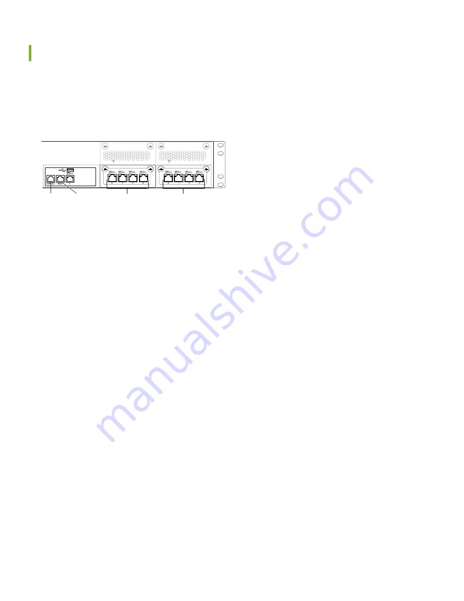
Connect the QFabric System Control Plane and Data Plane
The initial connection and configuration of your Juniper Networks QFX3000 QFabric System are beyond the scope of
this quick start. The following steps provide an overview of the tasks required to complete the setup process for your
QFabric system. The port connections are specific and cannot be described fully here. For a detailed description of the
port connections, see the deployment guide for your QFabric system at
g050068
USB
Management
Ethernet port
Console
port
Ports 1-4
Ports 5-8
1. Install a second QFX3100 Director device. Together the two Director devices form a Director group. The second
Director device provides redundancy for the QFabric system control plane and management network.
2. Connect network module ports on the first QFX3100 Director device to the second Director device. See the QFabric
system control plane example in the deployment guide for your QFabric system at
3. Using the connection diagram in the deployment guide, connect network module ports on the QFX3100 Director
device to Juniper Networks control plane Ethernet switches. This connects the Director device to the control plane
for your QFabric system.
4. Connect your Interconnect devices and Node devices to the control plane Ethernet switches.
5. Connect the QSFP+ uplink ports on each Node device to the 40-Gigabit Ethernet QSFP+ ports on your Interconnect
devices. Connect the 10-Gigabit Ethernet or Fibre Channel ports on the Node devices to servers or storage devices.
These connections form the data plane for your QFabric system.
6. Connect your management network to the management Ethernet port on both Director devices.The management
Ethernet (MGMT) port is located on the left side of the front panel of the Director device.
4


