background image

Chapter 3.

6

Installing MWS1000

To install a MWS1000:
1. Place the shipping container on a flat surface and remove the hardware components.

2. Attach the supplied mounting ears and brackets based on whether you intend to use a front-mounting

method or a mid-appliance mounting method.

3. Lift the appliance and insert it in the desired location in the rack. We recommend that you install the

appliance with two people; one to lift and one to put the screws in.

4. Align the holes on the mounting brackets with the holes on both sides of the equipment rack.

5. Secure the appliance to the rack.

6. Connect power to the appliance.

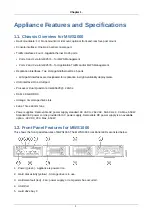
7. To connect to a local management device, plug the supplied cat-5 cable into the console port on the front

panel.

8. To connect to your network, plug cat-5 cables into Ethernet ports 2 or 3 on the front panel.

9. For a High Availability set up, plug the 10GbE cable into port 0 or 1 on the 10GbE NIC. (They will be

configured as eth4 and eth5 in the setup, respectively.)

10. Power on the appliance. When you turn on the power, the internal port uses its two LEDs to indicate the

LAN connection status.

3.1. Connecting Power to AC-Powered MWS1000

The power supply in a Virtual Services Engine is located on the rear panel. To connect AC power to the
appliance, plug both cords in and then turn the power on.

3.2. Connecting Power to DC-Powered MWS1000

Warning

Before performing DC power procedures, ensure that power is removed from the DC circuit.
To ensure that all power is off, locate the circuit breaker that services the DC circuit, switch
the circuit breaker to the off position, and secure the switch handle of the circuit breaker in
the off position.

Important

Do not mix AC and DC power supplies within the same appliance. Damage to the appliance
might occur.

Ensure that the equipment rack is properly grounded and the appliance has a good low-resistance ground
bond to the rack before you connect power to the DC power supplies.

Содержание MWS1000

Страница 1: ...Mykonos Web Security 4 95 8 Hardware Guide...

Страница 2: ...Mykonos Web Security 4 95 8 Hardware Guide This document contains a specification for the MWS1000 hardware appliance as well as instructions for installation into a server environment...

Страница 3: ...on 3 2 1 Clearance Requirements for Airflow and Hardware Maintenance for MWS1000 3 2 2 Power Specifications 3 2 3 Unpacking and Inspecting the MWS1000 4 2 4 Before You Install MWS1000 4 3 Installing M...

Страница 4: ...n High Availability deployments USB interface One USB port Processor Dual Quad core Intel E5620 2 4Ghz RAM 48 GB DDR3 Storage Six storage drive slots Fans Three 40 mm fans Power supplies Removable AC...

Страница 5: ...he MWS1000 has an Input Output Controller with two 10 Gb RJ 45 Ethernet ports labeled 0 and 1 Depending on your order configuration the front panel drive bays may or may not be configured The MWS1000...

Страница 6: ...e Maintenance for MWS1000 When planning the installation site allow sufficient clearance around the rack For the cooling system to function properly the airflow around the chassis must be unrestricted...

Страница 7: ...ch unit 10 Document any damage noted during your inspection 11 Confirm that the platform has the correct number and type of modules for your ordered configuration If you detect or suspect damage to an...

Страница 8: ...only copper grounding conductors For a ground wire attaching directly to the rack we recommend using the following ground lug Panduit P N LCDX8 10A L 8 AWG 10 stud 0 625 inch spacing To ensure a reli...

Страница 9: ...0GbE cable into port 0 or 1 on the 10GbE NIC They will be configured as eth4 and eth5 in the setup respectively 10 Power on the appliance When you turn on the power the internal port uses its two LEDs...

Страница 10: ...s maintain the proper polarity The power source cables may be labeled and to indicate their polarity There is no standard color coding for DC power cables The color coding used by the external DC powe...

Страница 11: ...3 3 RJ 45 Console Connector Pinout Table 3 1 RJ 45 Console Connector Pinout reference Pin Description 1 RTS Output Request to Send 2 DTR Output Data Terminal Ready 3 TxD Output Transmit Data 4 GND Cha...

Отзывы: