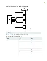
Table 15: T1/E1 Interface Module—RJ-45 Connector Pinout
Signal
RJ-45 Pin
RX Ring
1
RX Tip
2
–
3
TX Ring
4
TX Tip
5
–
6
–
7
–
8
RELATED DOCUMENTATION
CTP2000 T1/E1 Interface Module | 13
CTP2000 FXS and FXO Interface Module Cables and Pinouts | 48
CTP2000 Series Console Cable Pinouts | 63
Cabling a CTP2000 T1/E1 Interface Module | 111
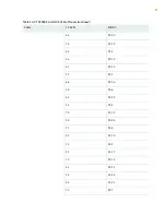
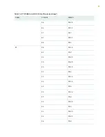
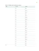
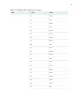
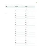
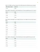
CTP2000 Serial Interface Module Pinouts
displays the serial DCE/DTE cable pin configurations for CTP2000 series devices.
52
Содержание CTP2000 Series
Страница 1: ...CTP2000 Series Circuit to Packet Platforms Hardware Guide Published 2020 08 31 ...
Страница 8: ...1 PART Overview CTP2000 Series Platform Overview 2 CTP2000 Series Interface Modules 11 ...
Страница 112: ...Installing SFPs in a CTP2000 Module 102 105 ...
Страница 127: ...5 PART Configuration Accessing the CTP2000 Platform 121 ...
Страница 144: ...7 PART Troubleshooting Troubleshooting Power Failures 138 Contacting Customer Support 140 ...
Страница 149: ...Locating CTP Component Serial Numbers 141 Returning CTP Products for Repair or Replacement 136 142 ...

