


Cabling a CTP2000 T1/E1 Interface Module
To install a cable in an interface module:
1. Ground yourself by using an antistatic wrist strap or other device, and connect it to an ESD grounding
jack, if available, or another grounding device.
2. Slide the cable as far as you can into the module until it clicks into place.
3. Gently pull the cable to confirm that it is inserted correctly.
4. Go on to
“Cabling the CTP Platform for DC Power” on page 111
For more information about T1/E1 interface module pinouts for the RJ-45 connector, refer
RELATED DOCUMENTATION
Required Tools, Wires, and Cables for the CTP2000 Platform | 109
CTP2000 Management Ports | 110
CTP2000 T1/E1 Interface Module | 13
Cabling the CTP Platform for DC Power
After you have correctly cabled the RTM for the CTP2000 Series, you must attach grounding and electrical
wires before you turn the device on.
Three main tasks are involved:
1. Push the power switch to OFF. (The switch might have accidentally flipped to ON during shipping and
installation.)
2. Connect the grounding wires to the chassis.
WARNING:
Always connect the grounding wires first (before connecting the power
cables) and disconnect them last when installing or servicing the device.
111
Содержание CTP2000 Series
Страница 1: ...CTP2000 Series Circuit to Packet Platforms Hardware Guide Published 2020 08 31 ...
Страница 8: ...1 PART Overview CTP2000 Series Platform Overview 2 CTP2000 Series Interface Modules 11 ...
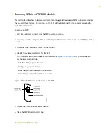
Страница 112: ...Installing SFPs in a CTP2000 Module 102 105 ...
Страница 127: ...5 PART Configuration Accessing the CTP2000 Platform 121 ...
Страница 144: ...7 PART Troubleshooting Troubleshooting Power Failures 138 Contacting Customer Support 140 ...
Страница 149: ...Locating CTP Component Serial Numbers 141 Returning CTP Products for Repair or Replacement 136 142 ...