


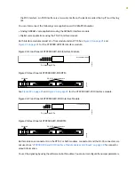


Figure 8: CTP2056 Chassis Containing the PP332 Processor (AC and DC Version, Front View)
USB
Optional fiber PMC
Power supply screw Power supply extractor
Interface module, slot 0
Interface module, slot 1
Interface module, slot 2
Interface module, slot 3
Interface module, slot 4
Interface module, slot 5
Interface module, slot 6
Fan tray with fan alarm
Removable air filter
g015389
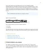
The front panel comprises the following components (see
):
•
Interface modules—Frame processing and forwarding engines.
•
Processor module—Two slots are available on this module for an optional fiber Gigabit Ethernet or Fast
Ethernet PMC module. The primary SC connector is on the left side. For more information about the
PMC module, see
“CTP2000 PMC Module” on page 30
and
“Installing a PMC on CTP2000 Platforms”
•
Power supply extractor—Push the button to eject the power supply module.
•
Fan tray and air filter.
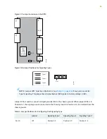
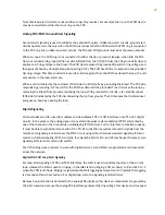
The rear panel (RTM) comprises the following components (see
and
•
Clock module—Provides clock distribution between modules when the backplane is in use by voice
applications.
•
Power supply—Use a standard IEC power cord for the AC version. Use a 22-AWG fork terminal connector
for the DC version. Power redundancy is supported for the AC version and the DC version. A single IEC
power cord is sufficient to connect the redundant AC power supply modules, which keeps the chassis
turned on in the event of failure of one of the power supplies.
There are no power switches on CTP2000 Series DC models, so a readily accessible disconnect device
must be provided as part of the electrical installation of the unit. We recommend the 22-AWG wire for
DC power terminals.
8
Содержание CTP2000 Series
Страница 1: ...CTP2000 Series Circuit to Packet Platforms Hardware Guide Published 2020 08 31 ...
Страница 8: ...1 PART Overview CTP2000 Series Platform Overview 2 CTP2000 Series Interface Modules 11 ...
Страница 112: ...Installing SFPs in a CTP2000 Module 102 105 ...
Страница 127: ...5 PART Configuration Accessing the CTP2000 Platform 121 ...
Страница 144: ...7 PART Troubleshooting Troubleshooting Power Failures 138 Contacting Customer Support 140 ...
Страница 149: ...Locating CTP Component Serial Numbers 141 Returning CTP Products for Repair or Replacement 136 142 ...