Copyright © 2011, Juniper Networks, Inc.
7
APPLICATION NOTE - Configuring and deploying the AX411 Wireless Access Point
The configuration is divided into three sections—the external, radio, and options sections.
The external section is used to specify the basic access point parameters used to manage the device, including its
address (when dhCP is not used), VLAN Id used for management traffic, and native VLAN Id (i.e., VLAN Id used for
untagged traffic).
In order to comply with the different regulatory domains, each access point must be configured with the name of the
country where it is being deployed. This is done under the access point options, and it is used to determine the range of
channels and maximum transmit power allowed in that domain.
finally, all radio, client authentication, and ssId options are configured under the radio section. The following
deployment scenarios will show some typical configurations, and they will be used to introduce some of the
configuration options available.
RADIuS Support
One or more (for redundancy purposes) rAdIus servers can be used to authenticate users. When a user is granted
access, the rAdIus protocol provides a mechanism to pass user-specific parameters to the access point. These
parameters allow passing per-user configuration options, centrally managed by the rAdIus server.
The following table displays the list of rAdIus attributes that can be passed to the AX411 access point, as specified in
rfC 3580.
Table 3: Supported RADIuS Attributes
ATTRIbuTe NAMe
VALue
Type
DeFINeD IN
session-Timeout
27
integer
rfC2865
Tunnel-Type
64
integer
rfC2868
Tunnel-Medium-Type
65
integer
rfC2868
Tunnel-Private-group-Id
81
integer
rfC2868
WIsPr-Max-Bandwidth-down
7
integer
VsA (14122)
WIsPr-Max-Bandwidth-up
8
integer
VsA (14122)
Description and Deployment Scenarios
We will start by configuring basic access point management access for both L2 and L3 modes. These configurations
will be used as the starting point in subsequent scenarios.
L2 Management Mode
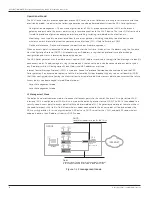
In this mode, all access points are connected to the srX series for the branch by means of an Ethernet switched
network, either using an external switch or the ports on the srX series gateway configured for switching. A single L3
interface is used to provide connectivity to all of the access points. This interface also serves as the default gateway for
the wireless clients.
Figure 3: L2 management mode example
INTERNET
OFFICE
vlan.1 (Trust)
192.168.1.1/24
ge-0/0/0.0
(untrust)
198.0.0.1/24
Client
AP-1
00:de:ad:10:75:00
AP-2
00:de:ad:10:76:00
AP-3
00:de:ad:10:77:00
DHCP
Handles out addresses in the 192.168.1.0/24
CorpNet SSID
A single broadcast SSID is advertised
SRX
Series


