background image

13

2 Instrument Description

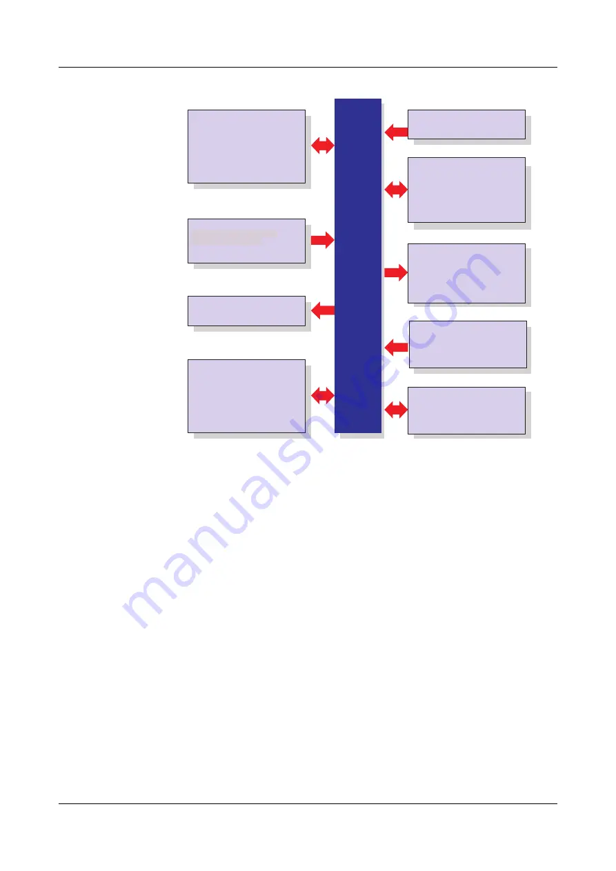
Block diagram

H

The connection diagram is described in the Installation 
Instructions B 706585.4(.1). When the paperless recorder is 
delivered, a printed version of the installation instructions is 
included.
B 706585.4

Installation instructions for recorder 
with zinc die-cast panel

B 706585.4.1

Installation instructions for recorder 
with stainless steel panel

Setup program,

PCA3000, PCC,

PCS, PCAT

Software

Internal channels

18

×

 math channels

18

×

 logic channels

27

×

 counters/integrators

Inputs/Outputs

0 to 18 analog inputs max.

0 to 24 binary inputs/outputs max.

(maximum of 3 module slots,

can be fitted with 6 analog inputs

or 3 analog inputs

and 8 binary inputs/outputs)

Display/Operation

JUMO LOGOSCREEN fd

Power supply

Display

Operation

5.5" TFT color display,
320 

×

 240 pixels,

256 colors

rotary knob or touchpad
(left, right, press)

additionally

up to 54 analog inputs and

up to 54 binary inputs

Inputs via interface

1 relay (standard)

additionally

6 relays (option)

Relay outputs

AC 100 to 240 V +10/-15 %,

48 to 63 Hz

AC/DC 20 to 30 V, 48 to 63Hz (ELV)

Interface

as standard

1

×

 RS232/RS485

option:

1

×

 PROFIBUS-DP

1

×

 Ethernet 10/100 Mbits/sec

4

×

 USB interfaces

1

×

 RS232 (barcode reader)

internal memory
256 Mbytes

external memory

CompactFlash card and

USB memory stick

Meas. data memory

Содержание LOGOSCREEN fd

Страница 1: ...JUMO LOGOSCREEN fd Secure Data Management and FDA Compliant Measured Data Recording B 706585 1 Operating Instructions 2014 05 22 00586143...

Страница 2: ...llowing additional functions are available with the new version additional horizontal recorder image applicable for curve presentation for binary presentation for display of a closed batch and for mem...

Страница 3: ...Activating the Operator Level 29 4 2 Overview of Header Lines 30 4 3 Curve Presentation 31 4 3 1 Vertical presentation 31 4 3 2 Horizontal presentation 32 4 4 Bar Graph Presentation 33 4 5 Text Pictur...

Страница 4: ...er 60 8 2 Log in and Log out 60 8 3 Device information 62 8 4 Device Audit Trail 67 8 5 Configuration 68 8 6 Parameterization 68 8 7 Service 69 9 Entering text and values 71 9 1 Text entry 71 9 1 1 En...

Страница 5: ...pages 83 10 4 Online Visualization of Current Batch Reports 84 10 5 QuadView 85 10 6 General information 88 10 7 Online visualization all visualizations other than batches 90 10 8 Online visualizatio...

Страница 6: ...Contents...

Страница 7: ...ng you are asked not to carry out any manipulations that could endanger your rights under the instrument warranty Please contact the nearest subsidiary or the head office in such a case E When returni...

Страница 8: ...r recorders with stainless steel front Instrument documentation in the form of PDF files The Instrument documentation in the form of PDF files is on the CD that is included in the delivery B 706585 0...

Страница 9: ...operation and the features of the PC Evaluation Software PCA3000 serves to visualize and evaluate process data measurement data batch data messages instrument audit trails The process data can be rea...

Страница 10: ...ocuments actions performed in the PC software components which lead to modifications of files user lists rights files device lists etc The different message types are Information Warnings and Errors A...

Страница 11: ...the instructions are ignored or not followed correctly E Warning This symbol is used where special care is required when handling components liable to damage through electrostatic discharge Note sign...

Страница 12: ...hat are displayed in the setup program are indicated by italic script Edit Device data Menu items Menu items in the setup and instrument software referred to in this operating manual are shown in ital...

Страница 13: ...ts max 0 to 24 binary inputs outputs max maximum of 3 module slots can be fitted with 6 analog inputs or 3 analog inputs and 8 binary inputs outputs Display Operation JUMO LOGOSCREEN fd Power supply D...

Страница 14: ...nal memory CF card located on front panel maximum 4 GB None Operation Control knob Touchpad Interfaces located on device s rear 2 USB 1 RS232 RS485 1 RS232 1 Ethernet 1 PROFIBUS DP option 2 USB 1 RS23...

Страница 15: ...s on continuously as soon as power is applied Status LED red is on continuously if an alarm is present Cover for the CompactFlash slot1 and the setup plug connection Control knob The control knob is u...

Страница 16: ...creen off USB host for data exchange measurement data configuration data user lists between the recorder and the PC USB device for communication with the setup program or PCC Header Status title bar E...

Страница 17: ...he rear side No interfaces at the front panel are available The installation instructions from B 706585 4 1 are to be heeded and complied with Power LED green is on continuously as soon as power is ap...

Страница 18: ...2 Instrument Description 18...

Страница 19: ...nel Function selection through a circular motion with a finger at the outer edge of the touchpad when activating the circular motion two of the eight LEDs in the touchpad are on Function selection by...

Страница 20: ...m and event lists Device manager v Chapter 8 Memory manager v Chapter 7 Alarm and event lists v Chapter 6 Operator level visualization v Chapter 4 Group selection v See Group selection on Page 31 Memo...

Страница 21: ...ation mode e g sampling rate It is automatically blanked out by the system if necessary Sampling rate and operating mode normal mode event mode timed mode If the text is shown in red this indicates an...

Страница 22: ...on or off also applies to the history presentation If the numerical measurement display is switched on in the history of the curve presentation you can switch between MIN and MAX display Whether or no...

Страница 23: ...indicated by a red or orange color for the curve can be configured in the setup program Communication with the operator device configuration checking alarm and event lists etc also takes place via the...

Страница 24: ...erating Principle 24 3 2 Operating Example Start The normal display is active Operation h Select the operator level by rotating the control knob h Activate the operator level by pressing the control k...

Страница 25: ...25 3 Operating Principle h Select the operator level by rotating the control knob h Activate the bar graph presentation by pressing the control knob Result The bar graph presentation starts...

Страница 26: ...as a total Each group can consist of a maximum of 6 analog inputs 6 binary inputs or outputs and 4 counters integrators The visualization and storage of the analog inputs and binary inputs outputs is...

Страница 27: ...Device manager Configuration Batches plants Gen plant parameters Number of plants A In order for a batch to be usable its main group must be active status Display or Display save and at least one ana...

Страница 28: ...3 Operating Principle 28...

Страница 29: ...ctivate the operator level by pressing the control knob You can alter the visualization after activating the operator level The functions in the header line will change depending on the visualization...

Страница 30: ...completed Counters and integrators Comment entry The comment entry does not have its own header The current header will remain when this function is activated The comment that has been entered is plac...

Страница 31: ...on the screen running from top to bottom Group selection You can use this function to directly select and display any one of the groups Group selection Memory presentation Numerical measurement displa...

Страница 32: ...the envelope display Channel step on This function activates the scaling display Repeated activation steps through the scaling for the channels within the group and then blanks it out again Group step...

Страница 33: ...tion to the analog channels the digital inputs can also be visualized at the bottom of the display If only digital channels are to be presented then Chapter 4 7 Binary diagram presentation is recommen...

Страница 34: ...s the digital inputs can also be visualized at the right hand edge of the display Group presentation 1 channel presentation Channel description Channel name Changeover to 1 channel presentation An ala...

Страница 35: ...and signals are visualized For this type of display one distinguishes between vertical and horizontal pre sentation Only one of the two presentation types can be active for all groups v Configuration...

Страница 36: ...usly displayed on the screen running from top to bottom 4 7 2 Horizontal presentation In the display signals are continuously displayed on the screen running from right to left The same functions as f...

Страница 37: ...n is used to switch between the various types of report for the current channel Channel step on This function can be used to switch between the individual channels of the group that is currently activ...

Страница 38: ...nt distinguishes between current batch and the most recently completed batch for a plant The number of plants that are used and the texts in the batch template can be configured on the instrument or i...

Страница 39: ...lants can be configured Start stop batch Use the parameter Device manager Configuration Batches plants Plant X General Batch start to configure how a batch starts and stops The following are available...

Страница 40: ...eport numerical presentation Attachments e g recipes h Rotate the control knob to select a type of presentation then press the knob to activate this type Activating the door symbol in the header close...

Страница 41: ...8 texts can be selected The con tent of the 128 texts can be edited with the setup program Line 2 The text in the left column is set in the Configuration menu through the Elec tronic signature Electro...

Страница 42: ...r code Every line that is to be set by the bar code must be configured Example for plant 1 line 1 program name Configuration Batch plant Batch Plant 1 Line 1 Content of right column bar code Activate...

Страница 43: ...d as follows Start batch h Scan bar code for Batch report for batch plant 1 3 h Scan start Stop batch h Scan bar code for Batch report for batch plant 1 3 h Scan stop H If a batch report is stopped th...

Страница 44: ...ponds to the bar code If several line have been configured for barcode activation then they will be processed one after another from top to bottom Reset entry Execution of the following bar code will...

Страница 45: ...in one screen template The functional characteristics counter integrator or operating hours counter are defined in the device configuration Overview presentation Individual presentation Overview of 9...

Страница 46: ...nd Event Lists v Chapter 4 3 Curve Presentation v Chapter 4 11 Comment Entry The text can now be found in the event list under the heading All events but also under the corresponding batch H If batche...

Страница 47: ...display completed batches For this type of display one distinguishes between vertical and horizontal pre sentation Only one of the two presentation types can be active for all groups v Configuration S...

Страница 48: ...ll lines Rotating the control knob moves the cursor through the visualization window The data in the Numerical measurement display are updated every time there is a shift If you move right up to the e...

Страница 49: ...ndow and activate the new zoom factor by pressing the control knob h Selecting Exit closes the dialog window and the presentation remains unchanged Fit to screen This function is only available for pr...

Страница 50: ...mode Channel step on This function activates the scaling display Repeatedly activating the function steps through the scaling for the channels within the group and then blanks it out again Close memor...

Страница 51: ...errors that are currently present Event lists Events list contain all the events that have occurred including all alarms and errors A The alarm list will not be updated as long as the window is open...

Страница 52: ...the control knob to select a list then press the knob to activate the list Activate event list First the directory tree for the event lists must be unfolded h Rotate the control knob to select an eve...

Страница 53: ...t a list then press the knob to activate the list Example In the example you can see a complete event list Close list h Close the event list by pressing the control knob The visualization that was act...

Страница 54: ...s shown in the list Close list h Close the event list by pressing the control knob The memory presentation that was active before the list was called up will now be displayed again 6 3 Symbols Power o...

Страница 55: ...ash memory card This shows the available internal memory for reading out data via the interface Activation for CF cards H Please note that depending on the user specific functions can be disabled thro...

Страница 56: ...is inserted the menu automatically appears and remains active until the memory stick is removed again If not all functions are available then you must log in to the device first in order to obtain the...

Страница 57: ...device from the data storage medium Save all update CF card All current reports will be concluded and written to the data storage medium together with the measurement data that have not yet been saved...

Страница 58: ...at had already been read After read out the data are marked as read in the recorder The function Backup CF card is therefore ideal for test and service work H Only one data storage medium can ever be...

Страница 59: ...logged in H The differences between No user logged in and User logged in only become visible in the Parameterization submenu Additionally differences are possible through the application of the PC Sec...

Страница 60: ...e changed by rotating the control knob Log in Log out Change password Close dialog H The paperless recorder is delivered ex factory with an internal user list which contains two users 1 User Master pa...

Страница 61: ...lly logged out after function calling Logging out with signature If it was established in the PC Security Manager Software PCS that a signatu re has to be executed when logging out proceed as follows...

Страница 62: ...e momentary values of all the internal and external inputs can also be checked The control knob can be rotated to display every single table The function is terminated by pressing the control knob Ver...

Страница 63: ...tom module slot Module 2 middle module slot Module 3 top module slot Date and time of last reconfiguration Switching state of relay 1 fitted as standard 0 not switched Bottom module slot Top module sl...

Страница 64: ...e picture below shows a module that has been fitted with 3 analog inputs and 8 binary inputs outputs Depending on the hardware level the picture may look different Module 2 is in the middle slot Displ...

Страница 65: ...dbus Master function Ext binary input BE The window shows the current external binary inputs External binary inputs are read into the recorder via one of the interfaces e g through the Modbus Master f...

Страница 66: ...ration Parameter Description Ethernet status 1 Received Ethernet packets Ethernet status 2 Received Ethernet packets with errors Ethernet status 3 Transmitted Ethernet packets Ethernet status 4 Transm...

Страница 67: ...to the configuration Parameters are also visible if there are no users logged in on the instrument 8 4 Device Audit Trail The audit trail contains a log of all user actions on the recorder The functio...

Страница 68: ...e access rights for these functions Only the setting of individual current batch numbers is enabled in the factory default setting v See B 706585 0 A An alteration of the configuration results in the...

Страница 69: ...rights for these functions Config factory settings The current configuration can be saved within the device as the new factory setting Restore factory settings The factory setting e g created by Set...

Страница 70: ...8 Device Manager 70...

Страница 71: ...y or function that will be performed when the control knob is pressed is shown in blue Available characters Cursor Close entry and confirm the text entered Close entry and discard the text input Shift...

Страница 72: ...l characters Special characters are entered as text h Select the symbol and press the control knob All the special characters that can be selected will now be shown Here too the selection and confirma...

Страница 73: ...press the control knob The character to the left of the cursor will be deleted 9 1 4 Move cursor h Select the cursor positioning button and press the control knob The cursor can now be moved To end s...

Страница 74: ...epted and the dialog window is closed The previously active setting is retained 9 2 Entry via selection field If a selection field is selected and then activated by pressing the control knob then the...

Страница 75: ...red to indicate that this digit can now be altered h Rotate the control knob to alter the tens digits and then confirm the entry by pressing the control knob The tens digit has now been altered and i...

Страница 76: ...ob The real number is indicated by a blue background h Rotate the control knob to move the cursor to the required position and then press the control knob Character deletion h Position the cursor h Se...

Страница 77: ...device Up to 187 03 xx v Chapter 10 1 General to Chapter 10 5 QuadView As of 187 04 xx v Chapter 10 6 General information to Chapter 10 9 QuadView H Which device software version is installed v Chapt...

Страница 78: ...herefore a device can also be accessed using the DNS names For visualizing graphics the SVG Viewer from Adobe must be installed on the PC in addition to Internet Explorer Log in A password query has b...

Страница 79: ...f the web server is started by the browser or if it has already been activated the user left clicks the Recorder link Areas The web server s display is divided into three areas Header Navigation Visua...

Страница 80: ...s recorder The most recent data are read from the device automatically every 3 seconds Online visualization v Chapter 10 2 Configurable device name read automatically Three freely programmable HTML pa...

Страница 81: ...to the configured groups of the recorder The sample screen shows the web server s home page This page can be used to represent channels in the same manner as on the recorder s screen Left click to bri...

Страница 82: ...10 Web server 82 Example Switching to bar graph presentation h Left click the Visualization menu h Left click the bar graph Result The bar graph visualization type is activated...

Страница 83: ...mmable HTML pages The sample screen shows one of three freely programmable HTML pages These pages can be created and modified with the setup program H Further information can be obtained from the inst...

Страница 84: ...the pages in the recorder if the factory setting of the instrument has been retained If plant data have been changed in the recorder HTML pages must be updated to reflect the changes Batch recording i...

Страница 85: ...be activated for each display for example two views of a device curve presentation and bar graph display Before QuadView can be used the function must be configured h Left click Setup Setup The setup...

Страница 86: ...Click Start or Start visualization Result QuadView starts In the example shown here two different recorders are accessed recorder 1 top left and top right recorder 2 bottom left and bottom right Two d...

Страница 87: ...online visualization the header contains modified buttons View all four visualizations View only top left visualization View only top right visualization View only top right visualization View only bo...

Страница 88: ...programs among others without a SVG viewer having to be installed Microsoft Internet Explorer 11 Mozilla Firefox 26 0 Google Chrome 32 0 The web server starts when the IP address e g http 10 11 101 1...

Страница 89: ...b server is divided into two areas Navigation Visualization area Navigation The individual pages can be accessed by clicking the left mouse button Online visualization v Chapter 10 7 Online visualizat...

Страница 90: ...ation area shows the current data from the paperless recorder Up dating occurs automatically through the web server 10 7 Online visualization all visualizations other than batches The operation confor...

Страница 91: ...he recorder are reset at the end of a record ing by the device and must be re sent Display available batch report Click text edit fields marked in yellow with the left mouse button and enter text once...

Страница 92: ...n and the bar graph display of a device in two views Before the 4 fold view can be used the function must first be configured Configuration h Left click h Enter the IP address or the DNS name in the c...

Страница 93: ...93 10 Web server Delete configu ration By left clicking the configuration will be deleted and new addresses can be entered...

Страница 94: ...10 Web server 94...

Страница 95: ...95 11 Appendix 11 1 Bar code 11 1 1 Batch control Plant 1 Plant 2 Plant 3 Start Stop Reset entry...

Страница 96: ...11 Appendix 96 11 1 2 Batch texts Product name SUPER PRODUCT NORMAL PRODUCT TOOTHED DISK 34 AXIS ROD 45 Product numbers 645736 012876...

Страница 97: ...97 11 Appendix 345435 Job numbers A83737 A4555455 A455445 Personnel number 4576 7665...

Страница 98: ...11 Appendix 98...

Страница 99: ...ture 40 Start manually 38 Batch start stop 39 Batch status 39 Batches 26 46 51 Binary 29 Binary display 35 Binary presentation 30 binary presentation 22 Block diagram 13 C CF card config data 57 CF ca...

Страница 100: ...ice manager 20 Diagram header 20 36 Diagram view 22 Display 15 17 Display off 16 Displays and controls 15 DNS 78 Documentation arrangement of 8 E Edit batch 39 Electrostatic discharge ESD 7 Entering v...

Страница 101: ...ntegrators 45 Introduction 7 IP address 78 88 K Keys 12 L Log in 60 Log in and Log out 60 Log out 60 M Max value 37 Memory manager 20 Memory managers 55 Memory presentation 20 31 47 Module 64 N Normal...

Страница 102: ...e 31 Save all update CF card 57 Screen saver 16 Screen texts 12 Scroll 48 Search 48 Service 69 Stainless steal 14 stainless steel 13 Status bar 16 21 Status LED 15 17 SVG 78 Symbols 23 54 T Text entry...

Страница 103: ...59 Standard default password 60 Standard default user 60 V Version 62 vertical presentation 31 36 Visualization 20 29 Visualization window 16 23 W Warning signs 11 Warranty 7 Web server 78 88 Writing...

Страница 104: ...12 Index 104...

Страница 105: ......

Страница 106: ......

Страница 107: ......

Страница 108: ...36035 Fulda Germany Phone 49 661 6003 0 Fax 49 661 6003 607 E mail mail jumo net Internet www jumo net JUMO House Temple Bank Riverway Harlow Essex CM20 2DY UK Phone 44 1279 63 55 33 Fax 44 1279 63 5...

Отзывы: