


11
TIGHTENING NEEDLE HEAD
When replacement of the needle bar, and or needle head is neces-
sary, torque the needle head to needle bar 14-16 in. lbs. (1.6-1.8Nm)
or use torque rod No. 21227AR that has been supplied with the
machine, for the purpose of eliminating the possibility of distorting
the needle bar due to overtightening. Insert the torque rod in the
hole at the upper end of the needle bar, while holding the needle
bar head with a suitable tool, turn the needle bar with the torque rod
onto the needle bar head. When the rod starts to bend, the needle
bar head has been threaded into the needle bar properly.
ALIGNING NEEDLES IN THROAT PLATE SLOTS
Insert a new set of needles, type and size specified, with screw (B, Fig.
4) slightly loosened, lower needle bar (A) and turn needle head as
required until the needles are centered in the throat plate needle
hole slots. Tighten screw (B) torque to 19-21in.lbs. (2.1-2.4Nm).
NOTE:
If the needles can not be aligned in the throat plate slots, the
lower cylinder must be moved as stated below.
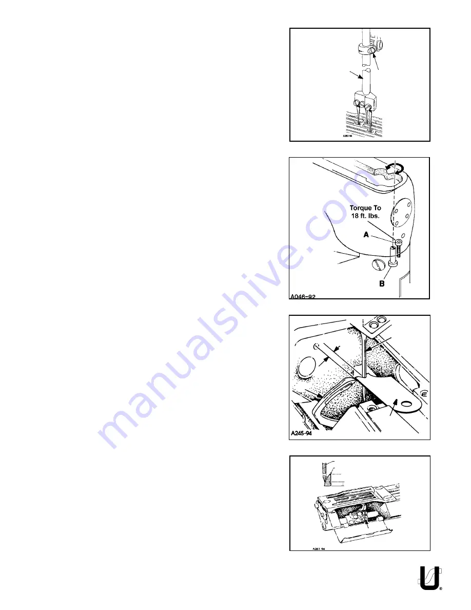
CENTERING THE CYLINDER
Remove the top front cover and gasket from the main frame. Loosen
cylinder holding screw (A, Fig. 5). Turn eccentric screw (B) clockwise
or counterclockwise to move the cylinder so the needles are
centered in the needle holes. Tighten screws (A) torque to 18 ft.lbs.
and recheck settings.
NOTE:
The cylinder may not move freely when the eccentric is
turned because the joint sealant compound has set.
SETTING THE LOOPER
Insert a new set of needles, type and size specified. Always adjust the
looper (A, Fig. 6) for the left needle first. Set the looper so that the
distance from the center of the needle (B) to the point of the looper
(A) is 9/64" (3.6mm) when the looper is at its farthest position to the
left. Looper gauge (C) No. 21225-9/64 can be used advantageously
in making this adjustment. If adjustment is required, loosen screw (A,
Fig. 7) in looper holder, permitting movement in either direction to
attain the 9/64" (3.6mm) dimension as shown in Fig. 6. Retighten
screw (A, Fig. 7). Repeat for other needles and loopers.
Rotate handwheel in operating direction to assure that the looper
point passes to the rear of the needle to touch but not deflect. This
adjustment can be made by loosening screw (A, Fig. 7) in looper
holder. Looper holder can be moved front to back to attain looper
to needle setting. Always check the 9/64" (3.6mm) looper gauge
setting after setting the looper to the back of the needle, and
conversely, always check the setting of the looper to the back of the
needle after setting the 9/64" (3.6mm) looper gauge.
The amount of looper avoid has been set at the factory to .110"
(2.8mm). If it becomes necessary to adjust the amount of avoid it is
recomended as a starting point, to have the points of the decending
needles contact the back of the lower 1/3 of the back of the
looper blade.
A
FIG. 4
Descending Needles
Looper Blade
Lower 1/3
FIG. 7
A
B
9/64"
(3.6mm)
C
B
FIG. 5
FIG. 6
A
Содержание UnionSpecial 35800DLU
Страница 7: ...7 THREADING OILING FOR PLAIN FEED FIG 1A...
Страница 8: ...8 THREADING OILING FOR DIFFERENTIAL FEED FIG 1B...
Страница 18: ...18...
Страница 20: ...20...
Страница 22: ...22...
Страница 24: ...24...
Страница 26: ...26...
Страница 28: ...28...
Страница 30: ...30...
Страница 32: ...32...
Страница 34: ...34...
Страница 36: ...36...
Страница 38: ...38...
Страница 40: ...40...
Страница 42: ...42...
Страница 44: ...44...
Страница 46: ...46...
Страница 48: ...48...
Страница 50: ...50...
Страница 52: ...52 2 3 4 1 5 27 26 25 7 24 6 8 9 10 23 22 11 12 15 14 13 16 11 13 18 19 5 21 20 17...
Страница 58: ...58 NOTES...
Страница 59: ...59 NOTES...
Страница 60: ......


