– 12 –
.24..ADJUSTING.THE.DRAW-OUT.AMOUNT.OF.THE.LOOPER.THREAD
The standard amount of looper thread is drawn out when looper
thread draw-out lever
1
is spaced 3 mm from the thread path
hole in cam thread guide
2
immediately before the thread
trimmer is actuated. Loosen nut
3
and make adjustment by
moving cam thread tension release slide block
4
to the right
or left.
For certain types of needle, the looper thread may slip off the
looper. In such a case, make adjustment so that a longer thread
is drawn out.
.25..REPLACEMENT.OF.GAUGE.PARTS
WARNING.:
To.avoid.possible.personal.injury.due.to.abrupt.start.of.the.machine,.turn.off.the.power.to.the.machine.and.check.to.be.sure.that.the.
motor.has.totally.stopped.rotating.in.prior.
WARNING.:
To.avoid.possible.personal.injury.due.to.abrupt.start.of.the.machine,.turn.off.the.power.to.the.machine.and.check.to.be.sure.that.the.
motor.has.totally.stopped.rotating.in.prior.
– 1 –
Model
MH-486-5
Sewing type
1-needle, double chainstitch, differential-feed, bottom and variable top feed machine
Sewing speed
Max. 4,500 sti/min
Stitch length
1 to 5 mm
Lift of presser foot
Hand lifter lever : 5.5 mm, Knee lifter : 7 mm
Top feed amount
0 to 7 mm
Stroke of needle bar
33 mm
Needle
Schmets 149 × 7 Nm 70 to Nm 130 (Standard : Nm 80)
Stitch length adjustment method
Dial type
Safety stitch
Condensation stitch/reverse-feed stitch (by feed lever)
Looper mechanism
Inclined crank type
Looper stroke
21.5 mm
Lubrication system
Fully automatic lubrication
Oil
JUKI New Defrix Oil No.1
Noise
- Equivalent continuous emission sound pressure level (L
pA
) at the workstation:
A-weighted value of 83.5 dB; (Includes K
pA
= 2.5 dB); according to ISO 10821- C.6.2 -ISO 11204
GR2 at 4,500 sti/min.
- Sound power level (L
WA
);
A-weighted value of 90.5 dB; (Includes K
WA
= 2.5 dB); according to ISO 10821- C.6.2 -ISO 3744 GR2
at 4,500 sti/min.
.1.. INSTALLATION
1) Carry the sewing machine with two persons.
.
(Caution). Do.not.hold.the.handwheel.
2) Do not put protruding articles such as the screwdriver and the like at the
location where the sewing machine is placed.
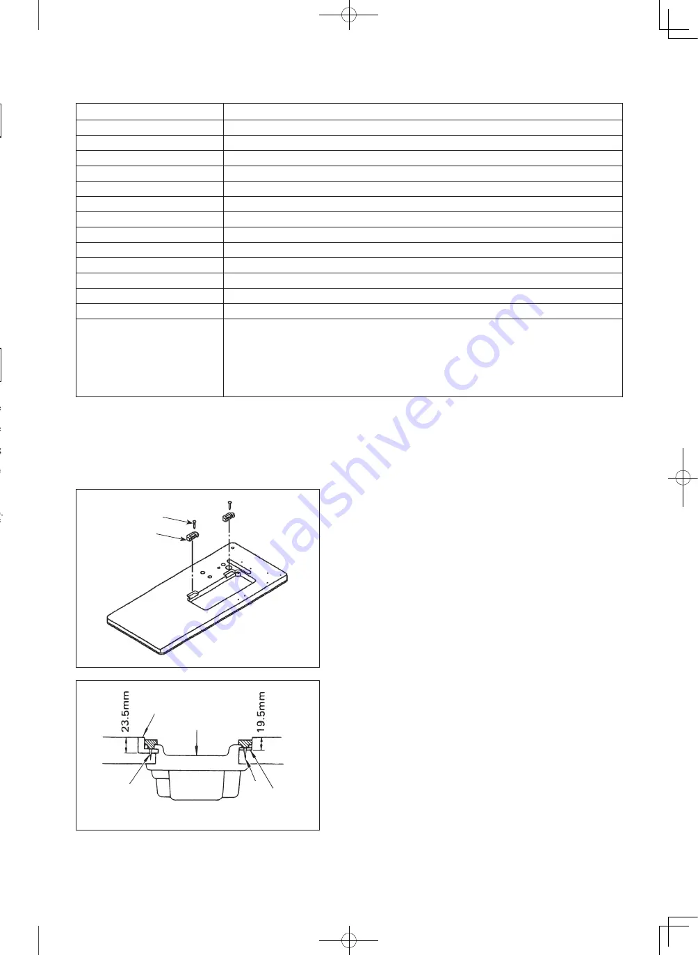
3) Attaching the hinge seats and the support rubbers of the machine head
Fix the hinge seats
1
supplied with the machine on the table using nails
2
.
1
2
4) Attaching the oil pan
Install oil pan
6
in such a way that it is supported at four corners of the
groove in the table.
At two corners on the operator's side, attach rubber cushion
3
to a protrud-
ing portion of the table by means of nails
4
. At two corners on the hinge
side, attach two head-rest cushions
5
by means of nails
4
. Then place oil
pan
6
on the cushions.
3
4
5
6
4
Hinge.side.
Operator’s.side
SPECIFICATIONS
Содержание MH-486-5
Страница 2: ......
Страница 27: ... 17 33 TROUBLES AND CORRECTIVE MEASURES ...
Страница 29: ... 19 ...
Страница 31: ......


