– 49 –
o If the wiper
is too long the
wiper will interface with the
needle clamp while the sewing
machine is no operation.
o If the wiper
is not correctly
positioned the wiper will interfere
with the needle clamp while the
sewing machine is in operation.
o If the wiper
is not correctly
positioned the wiper
will come
in contact with the needle while
the wiper is in operation. (The
needle may breaks.
1. Loosen the screw
and then tighten it in the position where a
clearance of 1.1
±
0.2mm is secured between the wiper base
and
the presser bar metal
.
2. Move the feed adjusting dial to MAX position.
3. Align the white engraved marker dot of the hand wheel to the en-
graved marker line of the pulley cover and move the wiper
by hand.
Loosen the screw
to adjust the wiper
and tighten the screw
again when the clearance has been adjusted to 2 to 3mm while the
wire tip comes closest to the tip of the wiper
.
4. Confirm that a clearance of more than 0.7mm is secured when the
pulley is turned and the wiper
comes closest to the needle clamp.
If the clearance provided between
the plunger radial plate and the
reverse stitching solenoid is larger
than the specified value:
o The attraction of the magnet will
be decreased. In this case, the
machine fails to start reverse
feed stitching.
If there is no clearance provided
between the plunger radial plate
and the reverse stitching magnet:
o The stitch length for reverse feed
stitching ill be decreased.
1. Set the stitch dial to the max. value on the scale.
2. Loosen two screws
in reverse feed solenoid mounting base
.
3. Press the reverse feed control lever
until it stops, and move the
plunger
in the direction of the arrow. Adjust the clearance to 0.5 to
1mm between the rubber washer
of the plunger
and the side
surface of the reverse feed solenoid
, and tighten the setscrew
.
* This adjustment should be carried out after confirming that
adjustments have been finished as per (15) Initial position of the
reverse feed control lever.
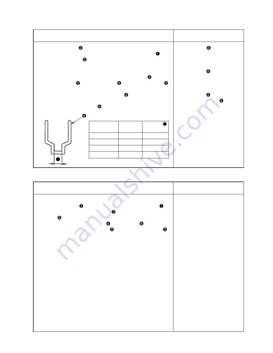
Gage size
Part No.
Dimension
A
(inch)
(mm)
3/22” to 3/8”
10209203
16
7/16” to 5/8”
10209500
24
3/4” to 7/8”
10209807
30
1” to 1 1/4”
10209906
37
A
Adjustment Procedure
Results of Improper Adjustment
Adjustment Procedure
Results of Improper Adjustment
Содержание LH-4128-7
Страница 11: ... 7 MEMO ...
Страница 30: ... 26 1 2 3 4 4 Oil in the feed box Standard Adjustment 5 Replacement of the hook shaft oil wick ...
Страница 34: ... 30 2 Center link section Standard Adjustment ...
Страница 46: ... 42 3 Adjusting the thread presser spring A Standard Adjustment ...
Страница 50: ... 46 6 Adjustment of thread tension release Standard Adjustment Clearance 0 ...
Страница 65: ... 61 MEMO ...
Страница 68: ... 64 10 Installation removal of the needle bar rocking base B A ...
Страница 86: ... 82 MEMO ...
Страница 88: ...MEMO ...


