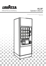
3) Diagram 3
– 206 –
CN60 [B]
1
2
+24V
Flap sensor (left)
Flap sensor (right)
GND
GND
GND
3
CN61 [B]
1
2
+24V
3
CN62 [B]
1
2
+24V
GND
+24V
Corner knife drawer detection SW
3
CN63 [B]
1
2
IN20B (Spare)
3
CN64 [B]
1
2
+24V
Bobbin thread remaining amount
detection sensor (left)
Bobbin thread remaining amount
detection sensor (right)
GND
3
4
5
+24V
GND
6
CN65 [B]
1
2
+5V
+24V
Lap start switch
3
4
GND
+5V
+24V
GND
CN66 [B]
1
2
IN22B (Spare)
3
4
CN67 [B]
1
2
Touch pedal SW
GND
CN68 [B]
1
2
Flap clamp pedal SW
GND
CN69 [B]
1
2
Pause SW
GND
CN70 [B]
1
2
Pocket bag clamp pedal switch
GND
CN71 [B]
1
2
+5V
+24V
Upper detection of flap supply (left)
Upper detection of flap supply (right)
3
4
GND
CN72 [B]
1
2
+5V
+24V
3
4
GND
CN73 [B]
1
2
+5V
+24V
Swing end (left) of flap supply
Swing end (right) of flap supply
3
4
GND
CN74 [B]
1
2
+5V
+24V
3
4
GND
CN75 [B]
1
2
+5V
Pedal sensor
GND
3
CN76 [B]
1
2
+5V
Pedal SW (Spare)
GND
3
CN77 [B]
1
2
+5V
IN7B (Spare)
GND
3
CN78 [B]
1
2
+5V
IN8B (Spare)
GND
3
CN79 [B]
1
2
Lower detection of fixed-side corner knife
GND
CN80 [B]
1
2
Upper detection of fixed-side corner knife
GND
CN81 [B]
1
2
Lower detection of moving-side corner knife
Upper detection of moving-side corner knife
GND
CN82 [B]
1
2
GND
CN84 [B]
1
2
3
4
5
6
7
8
9
10
11
12
13
14
15
16
17
18
19
20
10
11
12
13
14
15
16
17
18
19
20
21
22
23
24
25
26
27
28
29
30
31
32
33
34
35
36
37
38
+24V
39
AIRV B6
40
STI1
41
GND
42
STI2
43
GND
44
+24V
45
AIRV B7
46
STI4
47
GND
48
5VLDP
49
NC
50
10
11
12
13
14
15
16
17
18
19
20
21
22
23
24
25
26
27
28
29
30
31
32
33
34
35
36
37
38
39
40
41
42
43
44
45
46
47
48
49
50
PCBB2
CN83 [B]
1
2
+24V
Solenoid valve for CB stacker material presser
Solenoid valve for CB stacker material presser
Solenoid valve for CB stacker material presser
Solenoid valve for CB stacker material clamp
Solenoid valve for CB stacker material clamp
Solenoid valve for CB stacker material clamp
Solenoid valve for CB stacker material wiper
Solenoid valve for CB stacker material wiper
Solenoid valve for CB stacker material wiper
Air cylinder sensor for clamp origin
Air cylinder sensor for material wiper origin
+24V
3
4
5
+24V
6
7
+24V
8
Solenoid valve for core material draw-out
Stacker material wiper origin sensor
Stacker material wiper origin sensor
Solenoid valve for core material cutter
Solenoid valve for core material feed
9
+24V
+24V
Stacker opening detection switch
Stacker opening detection switch
Stacker opening detection switch
GND
GND
Stacker origin sensor
Stacker origin sensor
GND
+24V
Spare solenod valve output
Spare solenod valve output
INT PCB [B]
CN3 2
1
2
+24V
+24V
+5V
3
4
+5V
5
GND
6
GND
7
GND
8
GND
+24V
+24V
+5V
+5V
GND
GND
GND
GND
9
SIG1
SIG2
SIG3
SIG4
SIG5
SIG6
SIG7
SIG8
SIG9
SIG10
SIG11
SIG12
SIG13
SIG14
SIG15
SIG16
SIG17
SIG18
SIG19
SIG20
SIG21
SIG22
SIG23
SIG24
SIG25
SIG26
SIG27
SIG28
SIG29
SIG30
SIG31
SIG32
SIG33
SIG34
SIG35
SIG36
SIG37
SIG38
SIG39
SIG40
SENS1
SENS2
MAIN PCB 3/4
CN165
1
Lap start switch
GND
2
CN50
1
2
+5V
+24VD
+24VD
3
4
24VRTN
5
24VRTN
6
PMOFF
7
SENS
8
CURH(N)
9
MDIR
10
STEP(P)
11
STEP(N)
12
GND
CN85 [B]
1
2
Power supply for marking light
CN85 [B]
1
2
Power supply for marking light
Power supply for marking light
GND
GND
CN85 [B]
1
2
GND
CN275
1
2
+5V
Pedal sensor
GND
3
-
4
CN115
1
Corner knife drawer detection SW
GND
2
1
2
3
1
2
3
CN51
1
2
+5V
+24VD
+24VD
3
4
24VRTN
5
24VRTN
6
PMOFF
7
8
9
10
STEP(P)
11
STEP(N)
12
GND
Micro switch for corner knife drawer detection
Lap start switch
Pedal hole pot sensor
CN283
1
2
3
6
4
5
7
8
9
10
13
12
11
14
1
2
3
4
5
6
8
9
10
11
12
13
14
7
1
2
3
4
5
6
7
9
11
13
8
10
12
14
+24V
+24V
+24V
+24V
GND
GND
GND
Solenoid valve manifold
Solenoid valve manifold
CN115
1
2
GND
Micro switch for stacker opening detection
Optional clamp bar stacker unit
15
16
17
15
16
17
Solenoid valve for core material draw-out
Solenoid valve for core material feed
Solenoid valve for core material cutter
Optional core material supply unit
Reflex optical sensor (left) for bobbin
thread remaining amount detection
Reflex optical sensor (right) for bobbin
thread remaining amount detection
Reflex optical sensor (left) for flap
material end detection
Reflex optical sensor (right) for flap
material end detection
CN52
1
2
+5V
+24VD
+24VD
3
4
24VRTN
5
24VRTN
6
PMOFF
7
8
9
10
STEP(P)
11
STEP(N)
12
GND
13
STEPCB
14
GND
Cylinder sensor for upper detection of
moving-side corner knife
Cylinder sensor for lower detection of
moving-side corner knife
Cylinder sensor for lower detection of
fixed-side corner knife
Cylinder sensor for upper detection of
moving-side corner knife
Pause micro SW
CN96
1
2
Pause SW
GND
SENS
CURH(N)
MDIR
SENS
CURH(N)
MDIR
60A-1
61A-1
62A-1
63A-1
64A-2
65A-2
66A-2
67A-2
68A-3
69-A3
70A-3
71A-3
72A-1
73A-1
74A-1
75A-1
76A-2
77A-2
78A-2
79A-2
80A-3
81A-3
82A-2
82A-5
AIRV B1
AIRV B2
AIRV B3
AIRV B4
AIRV B5
Vertical reference laser marking light
(fixed-side)
Vertical reference laser marking light
(moving-side)
Optional laser marking light
Optional pattern coordination marking light
Содержание APW-895
Страница 14: ...7 Adjusting the bobbin thread trimming knife 9 A B Standard Adjustment ...
Страница 22: ...15 Wiper adjustment 17 A B C D E F 5 1mm 21 1mm Standard Adjustment 1 mm 0 0 5 ...
Страница 28: ...18 Adjustment of floating amount of the thread tension disk 23 A B Same surface Standard Adjustment ...
Страница 60: ...20 Pedal and related sections 55 A B Standard Adjustment B A ...
Страница 64: ... 3 Optional sections 1 SA 117 dart stretcher unit 59 1 Installation A B 2 Adjustment Standard Adjustment ...
Страница 66: ... 61 1 Installation of the shim bracket 2 SA 118 shim unit Standard Adjustment ...
Страница 68: ... 63 Adjustment of interlining clamp parallelism Standard Adjustment ...
Страница 70: ...3 SA 119 suction unit 65 Standard Adjustment ...
Страница 72: ... 67 Section A Standard Adjustment ...
Страница 74: ... 69 Section A Standard Adjustment Section B ...
Страница 151: ... 146 ...
Страница 152: ... 147 ...
Страница 153: ... 148 ...
Страница 154: ... 149 ...
Страница 155: ... 150 ...
Страница 158: ... 153 3 Spots where grease adhesive agents are used EXTERIORS A JUKI Grease A A A ...
Страница 159: ... 154 MAIN SHAFT THREAD TAKE UP LEVER COMPONENTS A JUKI Grease A G Three Bond 1373N A A G A A A G A A G A ...
Страница 160: ... 155 NEEDLE THREAD TRIMMER COMPONENTS A JUKI Grease A C Locktight 242 A A C A ...
Страница 161: ... 156 THREAD TENSION WIPER COMPONENTS A JUKI Grease A A A ...
Страница 162: ... 157 LOWER THREAD COMPONENTS A A C A A A C A JUKI Grease A C Locktight 242 A ...
Страница 163: ... 158 CENTER KNIFE COMPONENTS A A A A A C A A A C C A A JUKI Grease A C Locktight 242 ...
Страница 164: ... 159 LOWER SHAFT COMPONENTS A JUKI Grease A G Three Bond 1373N G A A A A ...
Страница 165: ... 160 HOOK DRIVING SHAFT LEFT COMPONENTS A JUKI Grease A A A A A A ...
Страница 166: ... 161 HOOK DRIVING SHAFT RIGHT COMPONENTS A JUKI Grease A A A A A A ...
Страница 167: ... 162 BACK TUCK COMPONENTS A JUKI Grease A G Three Bond 1373N G A ...
Страница 168: ... 163 CLAMP FOOT UNIT 1 B B B C B B B B C B JUKI Grease B C Locktight 242 ...
Страница 169: ... 164 CLAMP FOOT UNIT 2 B JUKI Grease B C Locktight 242 B B B B B C B B B ...
Страница 170: ... 165 CLAMP FOOT UNIT 3 B JUKI Grease B C Locktight 242 B C B B B B B B ...
Страница 171: ... 166 CLAMP FOOT FEED UNIT B JUKI Grease B D Locktight 243 D D B B B ...
Страница 173: ... 168 BINDER UNIT B JUKI Grease B D Locktight 243 D B B B B B B ...
Страница 174: ... 169 MARKING LIGHT UNIT D B D B F B B JUKI Grease B D Locktight 243 F Locktight 641 ...
Страница 175: ... 170 FRAME AND COVER COMPONENTS 1 B JUKI Grease B G Three Bond 1373N H Cemedyne Super X Clear G H B ...
Страница 176: ... 171 FRAME AND COVER COMPONENTS 2 B JUKI Grease B B ...
Страница 177: ... 172 FLAP PATTERN MATCHING MARKING LIGHT UNIT SA 121 B JUKI Grease B PEDAL SWITCH COMPONENTS B JUKI GreaseB B B B ...
Страница 179: ... 174 B JUKI Grease B G Three Bond 1373N AUTOMATIC INTERLINING FEEDER UNIT SA 120 B B G B B G ...
Страница 180: ... 175 ROLLER STACKER UNIT SP 47 B JUKI Grease B G Three Bond 1373N B B B B B G B G G B B ...
Страница 206: ... 201 MEMO ...