


ġ
2-8
2
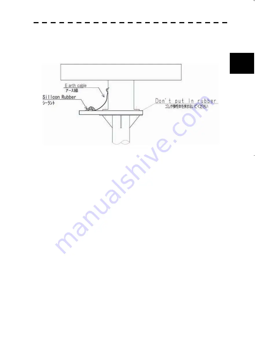
d) Grounding and corrosion-resistant measures
x
Ground the antenna chassis and the installation surface (hull) by using an earth line.
Apply sealant to the connection portion of the earth line to prevent corrosion and
damage by vibration (Fig. 10).
Fig. 10 Grounding and corrosion-resistant measures
Содержание JMA-5212-4
Страница 2: ......
Страница 6: ...ġ ...
Страница 8: ...ġ ...
Страница 9: ...SECTION 1 OVERVIEW ...
Страница 20: ...2 9 2 3 CONNECTING THE INSTALLATION CABLE NKE 2103 ...
Страница 21: ...ġ 2 10 2 ...
Страница 22: ...2 11 2 4 CONNECTING THE INSTALLATION CABLE NKE 2254 ...
Страница 23: ...ġ 2 12 2 ...
Страница 24: ...2 13 ...
Страница 37: ...3 12 3 Method of assembling and connecting P3 LTWBD06BFFA LL7001 and P5 LTWBD08BFFA LL7001 that are attached ...
Страница 65: ...3 40 3 2 Setting The target tracking function can be used simply by connecting it No setting is required ...
Страница 137: ...SECTION 6 INSPECTION AFTER INSTALLATION 6 1 INSPECTION AFTER INSTALLATION 6 1 6 2 OPERATION INSPECTION 6 1 ...
Страница 139: ...APPENDIX ...
Страница 140: ...Fig 1 NKE 2103 4 Outside Drawing ...
Страница 141: ...Fig 2 NKE 2103 6 Outside Drawing ...
Страница 142: ...Fig 3 NKE 2254 7 Outside Drawing ...
Страница 143: ...Fig 4 NKE 2254 9 Outside Drawing ...
Страница 144: ...Fig 5 NWZ 164 Outside Drawing ...
Страница 145: ...Fig 6 NDC 1460 Outside Drawing ...
Страница 146: ...Fig 7 NCE 7699A Outside Drawing ...
Страница 147: ...Fig 8 NBA 5111 Outside Drawing ...
Страница 149: ...Fig 10 GENERAL SYSTEM DIAGRAM OF RADAR TYPE JMA 5222 7 9 ...


