


18
139405_A CF
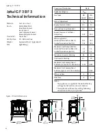
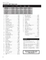
3
BF
3
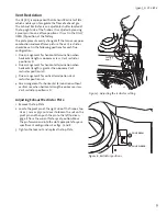
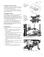
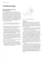
When There is No Gas Supply to the
Burner.
This is the trouble-shooting procedure for the electrical
components:
1. Make sure the control knob on the valve is set to “ON”.
Check the position on the “ON/OFF/Thermostat” switch
at the back of the appliance. It should be set to the ON
position.
2. Make sure the wire from the valve to the “ON/OFF/
STAT” switch is connected correctly.
This is the trouble-shooting procedure for the thermopile
(fig. 23):
1. Make sure the gas pressure is correct (see section
about gas pressure, page 12).
2. Make sure the pilot burner has 3 flames.
3. Make sure the flame is centred on the thermocouple.
4. Make sure the thermocouple is enveloped by the flame
up to at least 10mm (3/8”) from the tip (fig. 17).
5. Check the wires to the thermopile for cracks or dam-
age.
6. Dismantle the wires from the vent.
7. Dismantle optional equipment, such as thermostat or
remote control.
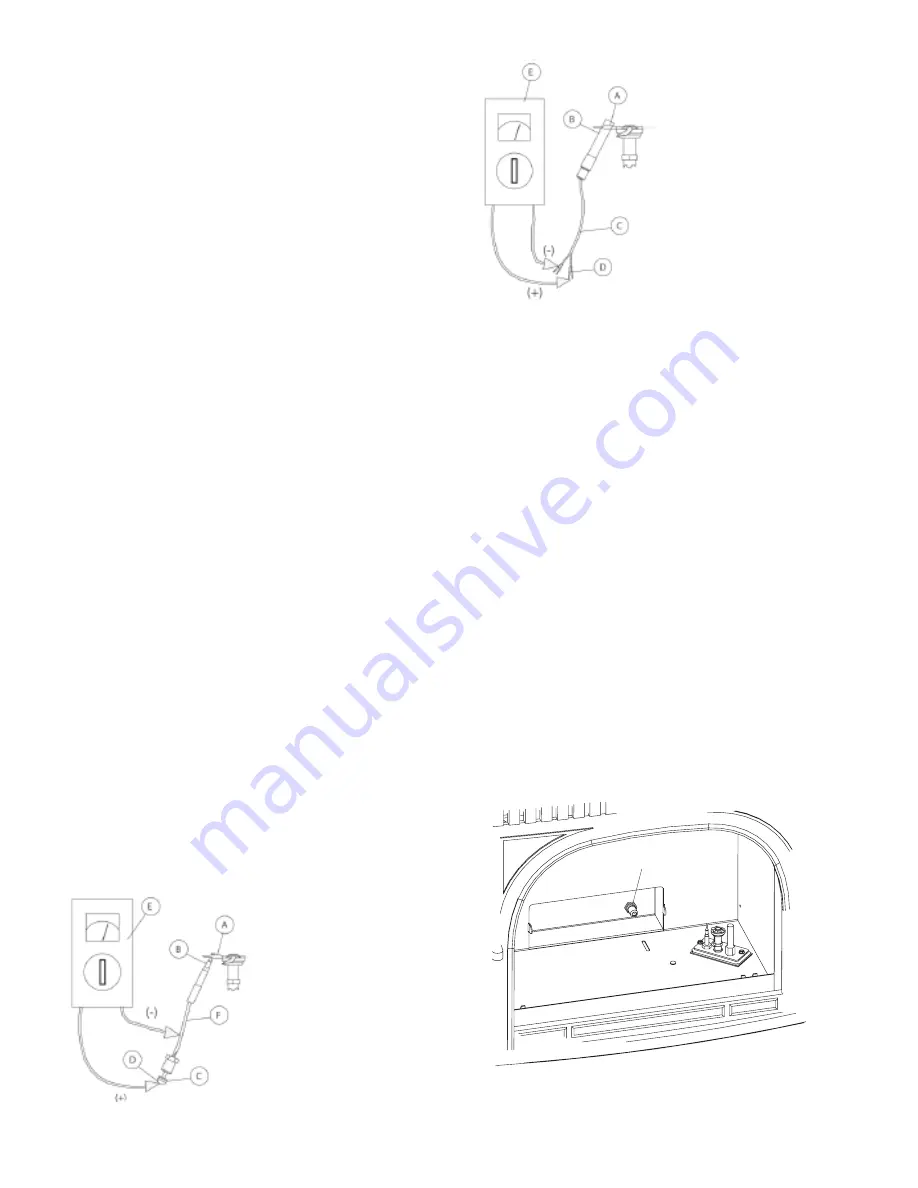
8. Check the voltage generated by the thermopile (see fig
24). Connect the multimeter with plus to one cable clip
(D). Connect minus to the other cable clip. Light the pi-
lot and make sure the control knob remains on “PILOT”
(fig. 20-B). At this point the multimeter should show
500-700 mV.
9. Reconnect the wires to the valve and make sure only
the ON/OFF/STAT switch is connected.
10. Turn the control knob on the valve to “ON” and turn the
ON/OFF/STAT switch to “ON”. At this point the multi-
meter should show more than 300 mV.
11. If a thermostat or remote control is to be connected, it
can be done now. At this point the multimeter should
show more than 175 mV.
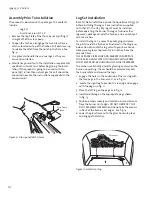
Problems With the Flame Pattern
Tall, narrow, yellow flames
These flames can soot the vent system and may result
from the following conditions:
• Insufficient Oxygen Supply -
For Propane and Natural
Gas, the air shutter should be fully open.
Loosen the air
shutter wing nut under the stove and pull it forward
(toward yourself) as far as it will go. See fig. 19.
Warning!
To avoid burns, do not adjust the air opening
until the burner has cooled down.
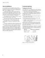
• Blocked Orifice -
Make sure the main orifice (fig. 25) is
dirt-free and that the orifice is the appropriate size. See
technical data.
• Poor draught
in the vent system may be due to
improper installation, or because the vent is not
inclined toward the chimney.
Tall, blue flames
The cause may be too much oxygen. Check for correct air
volume by measuring the opening (fig. 19) at the air shut-
ter. The cause may also be that the gas pressure is too
high. Also confirm the correct gas pressure as described in
the section on page 12.
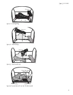
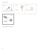
Figure 24.
Thermocouple
system check.
Figure 24.
Thermopile system
check.
Burner Orifice
Figure 25. Check main burner orifice for debris blockage.
Burner pan is removed.


