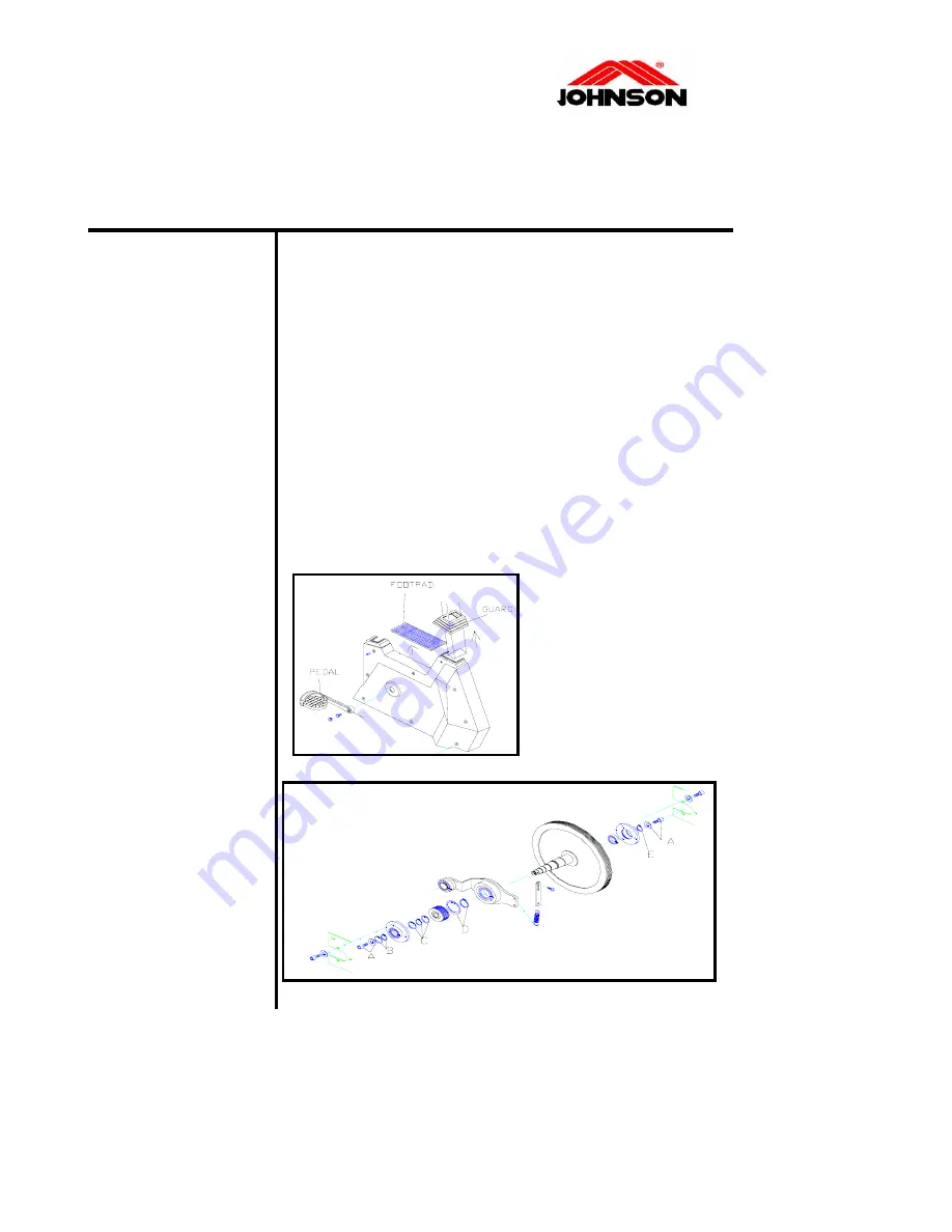
PEDAL AXLE-PULLEY ASSEMBLY REPLACEMENT
PROCEDURE
ools required:
Philips screwdriver
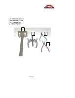
C-clip pliers
Crank extractor
Coin
Hex key (4mm)
ch
(14&17 mm)
1.
iver, then remove footpad, guard and
2.
e
3.
e
ng
is
operation
so you will not damage both you and
e front
4.
ove the
Bearing Housing
T
Open-end wren
Pr cedure:
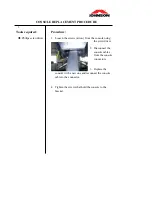
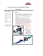
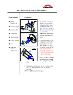
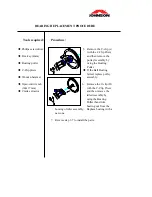
Remove the crank cover and screw, then remove the
crank.
Loosen the screws from the side cover with
the screwdr
o
side cover.
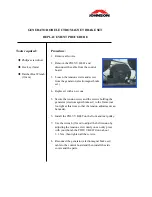
Loosen the screw (A) and remove it (for th
axle-pulley assembly of the new design).
Remove the spring attaching the idler pulley to th
frame first, then loosen the screws attaching the
bearing housing to the axle-pulley assembly usi
the hex key (4mm)
(The spring replacement
dangerous. Take special cautions during the
other
parts, then
remove th
pulley)
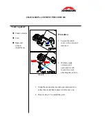
Remove the c-clip
(B) by using the
c-clip pliers and
using the Bearing
Puller rem
Содержание C7000
Страница 1: ...C7000 Service Manual Revision 1 0 Date 2004 7 25 ...
Страница 7: ...SECTION 2 EXPLODED DIAGRAM CONTENTS C7000 EXPLODED DIAGRAM ...
Страница 8: ...C7000 EXPLODED DIAGRAM ...
Страница 9: ...SECTION 3 WIRING DIAGRAM CONTENTS CONTROL BOARD WIRING DIAGRAM WIRING DIAGRAM ...
Страница 11: ...WIRING DIAGRAM ...
Страница 24: ...SECTION 5 1 GENERAL Contents CONSOLE CONSOLE CABLE CONTROL BOARD GENERATOR OR ELECTROMAGNET BRAKE SET ...
Страница 28: ...SECTION 5 2 Contents CRANK PEDAL POLY V BELT 400 380J6 POLY V BELT 500 440J8 AXLE FRONT PULLEY BALL BEARINGS ...
Страница 38: ...SECTION 6 MAINTENANCE PROCEDURE CONTENTS CLEANING THE GROOVES ...
Страница 41: ...APPENDIX 1 WOODEN HAMMER 2 BEARING PULLER 3 C CLIP PLIERS 4 C CLIP PLIERS 1 2 3 4 ...

