3.1 ELEC
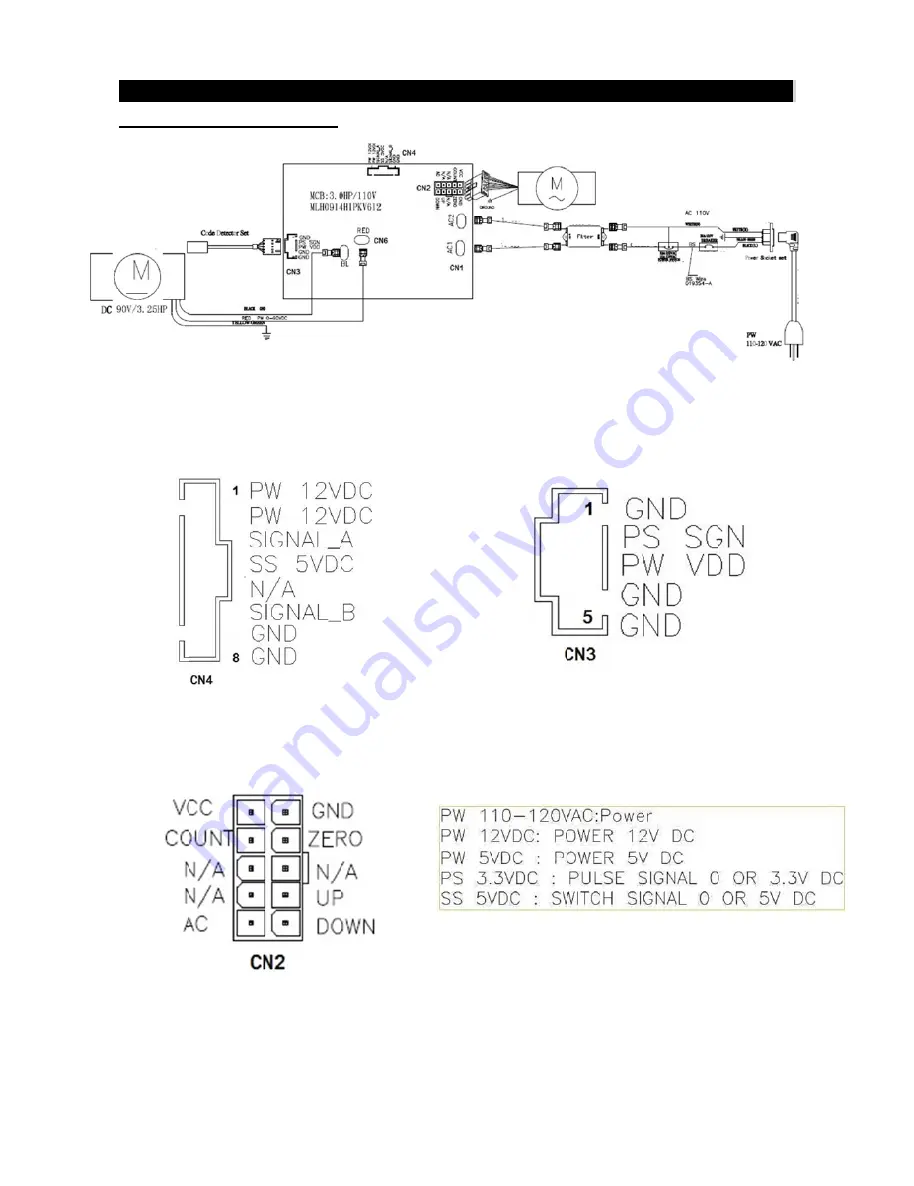
Fig-1 : The
Fig-3 The J
CTRICAL D
CN4 MCB
JP1 MCB To
DIAGRAM
B TO Cosole
o Inline Pin lo
CHAPTER
Pin layout
ocation
R 3: Trou
F
bleshootin
Fig-2 The JP
Fig-4 T
g
P6 Speed se
The Voltage
ensor to MCB
range instr
8
B pin layout
ruction
8
t
All manuals and user guides at all-guides.com


