background image

©2010 Johnson Level & Tool - Rev. 1

11

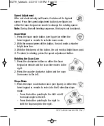
2. Press the slope mode button again to select Y-direction slope.

- Press the button pointing to the left to shift the slope angle to

the left.

- Press the button pointing to the right to shift the slope angle to

the right.

3. Another press of the slope mode button changes back to 

X-direction slope selection. Pressing and holding the button returns
the unit to normal operation.

Notes:

• When the unit is in TILT mode, pressing the slope mode button will

exit you from the TILT mode and into the slope mode.

• When using the unit in the vertical position, open the vertical

bracket and place the silver vertical foot over the desired location.
Adjust the vertical adjustment knobs to center the bubble in the
circle.  When using the slope mode in Y-direction the vertical beam
can be moved to the left or right. 

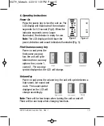
Timed Auto-off Function

Turn the unit on using the power button on the instrument keypad.
Press the power button once on the remote control. The unit is now 
in sleep mode.  The rotating beacon and laser beam will be 
powered down.

If the unit is in sleep mode for 30 continuous minutes, the unit turns off
automatically. With a second press of the power button on remote control,
the unit exits sleep mode and enters self-level mode.

3327H_Manuals  4/23/10  1:09 PM  Page 11

Содержание 40-6522

Страница 1: ... before using the instrument Save this instruction manual for future use This tool emits one rotating laser beam plus one plumb beam and is ideal for laying out indoor or outdoor construction projects Since the product is equipped with a laser beam detector visibility of the beam in various lighting conditions is not an issue This is a Class IIIa laser tool and is manufactured to comply with CFR 2...

Страница 2: ...ion Demonstrations 11 Care and Handling 12 Product Warranty 13 Warranty Registration 14 Accessories 1 Kit Contents Description Model No 40 6522 Qty Electronic Self Leveling Rotary Laser Level with Integral Vertical Mount 1 Ni MH Rechargeable Battery Pack 1 6V Battery Adapter 1 Remote Control with 9V Battery 1 Detector with 9V Alkaline Battery and Clamp 1 Magnetic Target 1 Tinted Glasses 1 Instruct...

Страница 3: ...the scan line size and scan direction Out of level alarm ensures the working accuracy Fine self calibration function Detector and remote control are included to make the laser ideal for all outdoor and indoor applications Slope function allows the user to perform slope in both X Y axis Dust and rain resistant 3 Safety Instructions Please read and understand all of the following instructions prior ...

Страница 4: ...ents i e in the presence of gases or flammable liquids Keep the laser tool out of the reach of children and other untrained persons Do not attempt to view the laser beam through optical tools such as telescopes as serious eye injury may result Always turn the laser tool off when not in use or left unattended for a period of time Remove the batteries when storing the tool for an extended time more ...

Страница 5: ... 2010 Johnson Level Tool Rev 1 5 4 Location Content of Warning Labels 3327H_Manuals 4 23 10 1 09 PM Page 5 ...

Страница 6: ...efore removing and replacing batteries Both Ni MH and C alkaline batteries not included can be used in the unit s battery compartment Unit ships with Ni MH battery packs installed 5 Location of Part Components Rotating Laser Output Window Handle Battery Compartment Cover DC 6V Battery Plug Laser Split Beam Output Window Keypad Integral Vertical Bracket Support Foot Vertical Circular Bull s Eye Lev...

Страница 7: ... disposed of properly Charging Ni MH Rechargeable Batteries 1 Remove black rubber plug above the battery compartment cover and insert the 6V battery adapter Plug adapter into 110V AC wall socket to begin charging When the charge indicator lamp turns from red to green after approximately five hours the Ni MH rechargeable battery pack has been fully charged Note 1 For the first two charges of new re...

Страница 8: ...n audible alarm You will need to re position the instrument inside of its self leveling range 3 Press power button to turn power on and press operation buttons on control panel or use remote control to adjust to your desired working status 4 After finishing operation or before moving the instrument turn the power off 7 Using the Product Place the unit on a relatively level surface like a tripod fl...

Страница 9: ...If the instrument is inclined beyond its auto leveling range of 5 it will deliver an audible alarm rotation will stop and the laser beam will flash You will need to re position the instrument within its self leveling range Height of Instrument H I 1 After powering on the instrument and entering into auto level status press the TILT button When the indicator light is on see figure the instrument en...

Страница 10: ...right laser line 3 With the third press of this button the unit emits a bright laser point 4 To return to rotating press the speed adjustment button Rotating the Scan Line 1 Press the clockwise button on either the laser keypad or remote and the scan line moves to the right 2 Press the counter clockwise button and the scan line moves to the left Slope Mode 1 Press the slope mode button once see fi...

Страница 11: ... unit in the vertical position open the vertical bracket and place the silver vertical foot over the desired location Adjust the vertical adjustment knobs to center the bubble in the circle When using the slope mode in Y direction the vertical beam can be moved to the left or right Timed Auto off Function Turn the unit on using the power button on the instrument keypad Press the power button once ...

Страница 12: ...n using rotary laser levels The main function of the detector is to detect the position of the laser signals that are transmitted by rotary lasers This detection quickly and precisely provides the user with the horizontal and vertical references This product features high sensitivity a double faced display low power consumption good reliability and easy manipulation It can be used with most types ...

Страница 13: ...and dust resistant 2 Components a Exterior Instruction 1 Horizontal vial 2 Front display window 3 Front on grade mark 4 Vertical vial 5 LED key 6 Power key 7 Beeper 8 Reception window 9 Fine Coarse accuracy key 10 Beeper key 11 Back display window 12 Back on grade mark 13 Bracket screw thread 14 Battery cover screw 15 Battery cover 2010 Johnson Level Tool Rev 1 13 3327H_Manuals 4 23 10 1 09 PM Pag...

Страница 14: ...y Cycles between high low and off 3 Operation Guide a Battery Installation Open the battery cover door by turning the battery cover screw counter clockwise Put the battery into the battery case noting the polarity shown in the battery compartment Put the battery cover door back and tighten the screw Note 1 Remove the battery when the unit is being stored for a long time 2 When the low battery indi...

Страница 15: ... illuminated Fig 3 Fine Coarse accuracy key Power on and press the fine coarse accuracy key the unit will cycle between three accuracy options fine coarse 1 coarse 2 The accuracy symbol displayed on the LCD will change Volume Key Power on and press the volume key the unit will cycle between a high sound low sound and mute The sound symbol displayed on the LCD will change accordingly Note There wil...

Страница 16: ... on grade mark decreases 1 When detecting a horizontal laser signal it is important to have the bubble vial centered as the deflection of the receiver will influence its receiving accuracy Laser signal The laser signal is down Sound rapid short beeps Laser signal The laser signal is up Sound slow short beeps Laser signal Horizontal bar indicated on grade Sound continuous sound No laser signal is d...

Страница 17: ...backlit Automatic Shut off Function When the unit does not receive a laser signal for 6 minutes the unit will power off automatically Low Battery Display Function When the battery sign blinks on the LCD the battery is low and needs to be replaced If the battery is very low the unit will power off automatically Replace the battery Rod Clamp Connecting to the rod clamp Connecting to the grade rod 5 ...

Страница 18: ...r tripod that is 50 away from a wall indoors with the X direction facing the wall head on Turn the unit on 3 Using the detector mark on the wall where the beam hits the wall and mark that as A 4 Turn the instrument by 180 degrees and mark the beam as point B 5 Measure the vertical distance between point A and point B If A B are more than 1 32 apart at 50 the unit is out of calibration 6 Turn the i...

Страница 19: ...ase the Power button When releasing the Power button all red LED s on the unit s keypad display will light up After about 10 seconds all LED s except the power LED will go off 3 Release the TILT button Note that the rotating head of the laser is not rotating but the laser is flashing The unit is now in calibration mode and all other operations will be performed with the unit s remote control 4 Ope...

Страница 20: ...trol to the X axis 4 Press the UP arrow and DOWN arrow buttons respectively to adjust the laser height to coincide with the zero position of the target 5 Press the ENTER button on the remote control to accept the calibration value noting that the status indicator goes OFF 6 After calibration is completed make sure to power off the unit and then power on again to activate the calibration Y Axis Cal...

Страница 21: ... activate the calibration Z Axis Calibration 1 Place the unit into calibration mode as discussed above 2 Position the unit so that the Z axis is directed to the two targets 3 Press the button on the remote control to toggle calibration control to the X axis 4 Press the UP arrow and DOWN arrow buttons respectively to adjust the laser height to coincide with the zero position of the target 5 Press t...

Страница 22: ...ter 60m with remote Slope 8 Self Leveling Range 5 Power Supply Rechargeable NiMH battery pack or 6V adapter included 4 C alkaline batteries not included Battery Life Approx battery life 15 hours continuous use with rechargeable battery pack 20 hours with 4 C alkaline batteries Dimensions 5 75 x 7 75 x 7 625 146 x 197 x 194mm Weight 4 4 lbs 2 Kg Working Temperature 14 F to 113 F 10 C to 45 C Center...

Страница 23: ...ation Reference for window installation Reference for squaring and leveling Reference for retaining wall installation Reference for cement floor installation Reference for fence Reference for trim installation and locating ceiling fixtures 10 Application Demonstrations 3327H_Manuals 4 23 10 1 09 PM Page 23 ...

Страница 24: ...anty on each of its products You can obtain a copy of the limited warranty for a Johnson Level Tool product by contacting Johnson Level Tool s Customer Service Department as provided below or by visiting our web site at www johnsonlevel com The limited warranty for each product contains various limitations and exclusions Do not return this product to the store retailer or place of purchase Non war...

Страница 25: ... Level Tool s Customer Service Department at 800 346 6682 13 Warranty Registration Enclosed with this instruction manual you will find a warranty registration card to be completed for your product You will need to locate the serial number for your product that is located on the bottom of the unit PLEASE NOTE THAT IN ADDITION TO ANY OTHER LIMITATIONS OR CONDITIONS OF JOHNSON LEVEL TOOL S LIMITED WA...

Страница 26: ...d any applicable limited warranty and there will be NO WARRANTY If you need any assistance in locating any accessories please contact our Customer Service Department In the U S contact Johnson Level Tool s Customer Service Department at 888 9 LEVELS In Canada contact Johnson Level Tool s Customer Service Department at 800 346 6682 3327H_Manuals 4 23 10 1 09 PM Page 26 ...

Отзывы: