


JOHNSON CONTROLS
296
FORM 201.23-NM2
ISSUE DATE: 3/9/2015
SECTION 8 - MICROPANEL
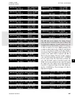
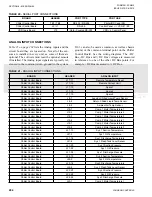
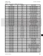
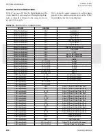
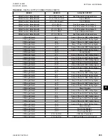
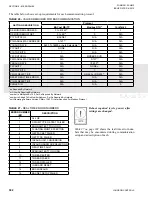
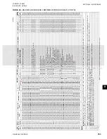
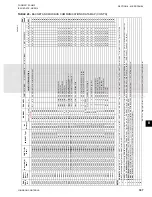
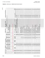
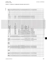
TABLE 22 -
DIGITAL INPUT CONNECTIONS
BOARD
HEADER
ANALOG OUTPUT
Chiller Control Board
J4-2
Unit Switch 1
Chiller Control Board
J4-3
Unit Switch 2
Chiller Control Board
J4-4
Sys 1 HPCO
Chiller Control Board
J4-5
Sys 2 HPCO
Chiller Control Board
J4-6
VSD Fault Relay 1
Chiller Control Board
J5-1
Sys 3 HPCO
Chiller Control Board
J5-2
Sys 4 HPCO
Chiller Control Board
J5-3
VSD Fault Relay (Unused)
Chiller Control Board
J6-2
Flow Switch
Chiller Control Board
J6-3
Chiller Control Board
J6-4
Sys 1/3 Run Permissive
Chiller Control Board
J6-5
Sys 2/4 Run Permissive
Chiller Control Board
J6-6
Spare
Chiller Control Board
J7-1 to J7-2
Config0
Chiller Control Board
J7-3 to J7-4
Config1
Chiller Control Board
J7-5 to J7-6
Config2
Chiller Control Board
J7-7 to J7-8
Config3
Chiller Control Board
J7-9 to J7-10
Spare 0
Chiller Control Board
J7-11 to J7-12
Spare 1
VSD Logic Board
J1-10
2 Compressor Select
VSD Logic Board
J1-11
3 Compressor Select
VSD Logic Board
J1-12
4 Compressor Select
VSD Logic Board
J5-1 to J5-2
VSD Logic Board
J5-3 to J5-4
VSD Logic Board
J6-2
Comp 1 Phase A Gate Driver Fault
VSD Logic Board
J6-5
Comp 1 Phase C Gate Driver Fault
VSD Logic Board
J6-12
Comp 1 Phase B Gate Driver Fault
VSD Logic Board
J7-2
Comp 3 Phase A Gate Driver Fault
VSD Logic Board
J7-5
Comp 3 Phase C Gate Driver Fault
VSD Logic Board
J7-12
Comp 3 Phase B Gate Driver Fault
VSD Logic Board
J7-2
Comp 2 Phase A Gate Driver Fault
VSD Logic Board
J7-5
Comp 2 Phase C Gate Driver Fault
VSD Logic Board
J7-12
Comp 2 Phase B Gate Driver Fault
VSD Logic Board
J8-2
Comp 4 Phase A Gate Driver Fault
VSD Logic Board
J8-5
Comp 4 Phase C Gate Driver Fault
VSD Logic Board
J8-12
Comp 4 Phase B Gate Driver Fault
VSD Logic Board
J11-2
Phase Loss Fault 1
VSD Logic Board
J11-6
Phase Loss Fault 2
VSD Logic Board
SW1
Test Pushbutton
VSD Logic Board
J10-5 to J10-6
Comp 1/3 Run (from control panel)
VSD Logic Board
J10-7 to J10-8
Comp 2/4 (from control panel)
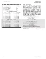
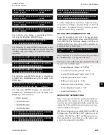
DIGITAL INTPUT CONNECTIONS
lists the digital inputs and the
circuit board they are located on. The Digital input sig-
nals are typically referenced to the common (return,
ground) in the system.
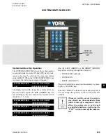
J12-3 can also be used as common, as well as chassis
ground, or the common terminal point on the Chiller
Control Board. See the wiring diagrams.
Содержание YCIV0157
Страница 18: ...JOHNSON CONTROLS 18 FORM 201 23 NM2 ISSUE DATE 3 9 2015 SAFETY SYMBOLS THIS PAGE INTENTIONALLY LEFT BLANK ...
Страница 38: ...JOHNSON CONTROLS 38 FORM 201 23 NM2 ISSUE DATE 3 9 2015 THIS PAGE INTENTIONALLY LEFT BLANK ...
Страница 42: ...JOHNSON CONTROLS 42 FORM 201 23 NM2 ISSUE DATE 3 9 2015 THIS PAGE INTENTIONALLY LEFT BLANK ...
Страница 50: ...JOHNSON CONTROLS 50 FORM 201 23 NM2 ISSUE DATE 3 9 2015 THIS PAGE INTENTIONALLY LEFT BLANK ...
Страница 104: ...JOHNSON CONTROLS 104 FORM 201 23 NM2 ISSUE DATE 3 9 2015 SECTION 6 TECHNICAL DATA Panel Layout 2 Compressor Models ...
Страница 105: ...JOHNSON CONTROLS 105 SECTION 6 TECHNICAL DATA FORM 201 23 NM2 ISSUE DATE 3 9 2015 THIS PAGE INTENTIONALLY LEFT BLANK ...
Страница 115: ...JOHNSON CONTROLS 115 SECTION 6 TECHNICAL DATA FORM 201 23 NM2 ISSUE DATE 3 9 2015 THIS PAGE INTENTIONALLY LEFT BLANK ...
Страница 119: ...JOHNSON CONTROLS 119 SECTION 6 TECHNICAL DATA FORM 201 23 NM2 ISSUE DATE 3 9 2015 THIS PAGE INTENTIONALLY LEFT BLANK ...
Страница 333: ...JOHNSON CONTROLS 333 FORM 201 23 NM2 ISSUE DATE 3 9 2015 NOTES ...


