background image

Series II Installation Manual Addendum

8

www.johnsoncontrols.com

LIT-12012316

Effective


May

 2017

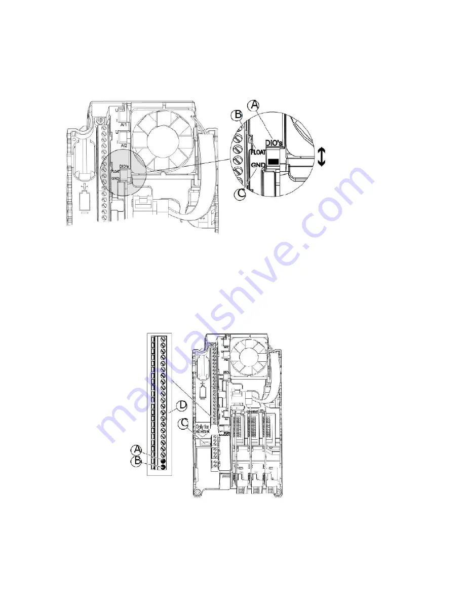
Digital input ground isolation

It is possible to isolate from ground the digital inputs (terminals 8-10 and 14-16) on the standard I/O
board. To do this, change the position of a DIP switch on the control board.

A. The digital inputs
B. Floating
C. Connected to GND (default)

Field Bus Connection

You can connect the drive to fieldbus with an RS485 or an Ethernet cable. If you use an RS485 cable,
connect it to terminal A and B of the standard I/O board. If you use an Ethernet cable, connect it to the
Ethernet terminal below the cover of the drive.

A. RS485 terminal A = Data –
B. RS485 terminal B = Data +
C. The Ethernet terminal
D. The control terminals

Содержание VSD II Series

Страница 1: ...Variable Speed Drive Series II LIT 12012316 JCI VSD Series II Installation Manual Addendum New control board update 525 600V offering Effective May 2017...

Страница 2: ...a Johnson Controls Return Mate rial Authorization RMA number prior to returning any defective product When purchased through an Authorized Distributor the Distributor should supply an RMA number to th...

Страница 3: ...son Controls PSO Team if you need assistance with placing an order stock availability or proof of shipment expediting an existing order emergency shipments product price information and returns includ...

Страница 4: ...Number Selection 10 Power Ratings and Product Selection 11 Mounting Drive Dimensions 12 Series II Technical Data 13 Cable Power and Motor Wiring Guidelines 15 Manual Addendum This manual is an addend...

Страница 5: ...ards A The control terminals for the standard I O connections B The Ethernet connection C The relay board terminals for 3 relay outputs or 2 relay outputs and a thermistor D The option boards E A DIP...

Страница 6: ...linking slowly Ready Green Run Red Fault Orange Alarm Blinking fast Downloading software Control Board Terminals Here is the basic description of the terminals of the standard I O board Control Wiring...

Страница 7: ...he DIP switches for specified terminals The switches have 2 positions up and down You can see the location of the DIP switches and the possible selections below A The voltage signal U 0 10 V input B T...

Страница 8: ...n of a DIP switch on the control board A The digital inputs B Floating C Connected to GND default Field Bus Connection You can connect the drive to fieldbus with an RS485 or an Ethernet cable If you u...

Страница 9: ...y board terminals and other terminals The terminal The terminal screw The tightening torque Nm lb in All the terminals of the I O board and the relay board M3 0 5 4 5 Battery for Real Time Clock To us...

Страница 10: ...0V Catalog Number Selection SERIES II Series Open Drives Notes All boards are varnished conformed coated Corrosion resistant Battery included in all drives for real time clock Three year lifetime Keyp...

Страница 11: ...Full Load Amps at 50 C 1 N1 IP21 2 N12 IP54 Catalog Number FR5 3 9 3 4 6 3 3 VS3D95_0B 00000 6 1 5 6 8 5 2 VS6D15_0B 00000 9 7 5 9 7 7 VS9D05_0B 00000 11 10 10 5 9 4 VS0115_0B 00000 FR6 18 15 19 9 15...

Страница 12: ...Line Voltage hp VT Amperes D H1 H2 H3 W1 W2 W3 Weight in Lbs FS5 600 Vac 3 10 3 9 11 8 73 16 5 15 98 15 04 5 67 4 53 3 94 22 FS6 600 Vac 15 30 18 34 9 29 21 93 21 28 20 24 7 68 5 83 5 83 44 1 FS7 600...

Страница 13: ...tion 0 1 3000 sec Ambient conditions Ambient operating temperature IL 10 C no frost to 40 C up to 50 C with derating Storage temperature 40 to 70 C Relative humidity 0 95 RH non condensing non corrosi...

Страница 14: ...pow er level in dB A FS5 65 FS8 73 FS6 72 FS9 75 FS7 73 Safety EN61800 5 1 2007 CE cUL see nameplate for more detailed approvals Protections Overvoltage trip limit 600V drives 1094Vdc Undervoltage tr...

Страница 15: ...9 7 7 10 14 10 20 5 17 8 011 10 11 9 4 15 14 8 20 5 17 8 FR6 018 15 18 15 20 10 8 13 0 13 2 022 20 22 18 25 10 8 13 0 13 2 027 25 27 23 30 8 8 13 0 13 2 034 30 34 28 40 8 6 13 0 13 2 FR7 041 40 41 34...

Страница 16: ...LIT 12012316 Effective May 2017 16 www johnsoncontrols com Building Technologies Solutions 507 E Michigan Street P O Box 423 Milwaukee WI 53201 2017 Johnson Controls All Rights Reserved Printed in US...

Отзывы: